GCM General Control Module
7
Dialup Connection
1. Connect P6 to the iSTAR modem as shown in Table 2.
2. Connect the host modem to a COM Port.
3. Set the COM Port to 57,600 baud, 8, None, 1, Hardware Flow Control.
4. Configure the RAS login information using ICU.exe
5. Configure the C•CURE 800 Server to accept RAS connections.
6. Configure the controller and cluster using ICU and the C•CURE 800.
Serial Connection
1. Connect P6 to the Server COM Port as shown in Table 3.
2. Set the COM Port to 57,600 baud, 8, None, 1, Hardware Flow Control.
3. Configure the RAS login information using ICU.exe
4. Configure the C•CURE 800 Server to accept RAS connections.
5. Configure the controller and cluster using ICU and the C•CURE 800.
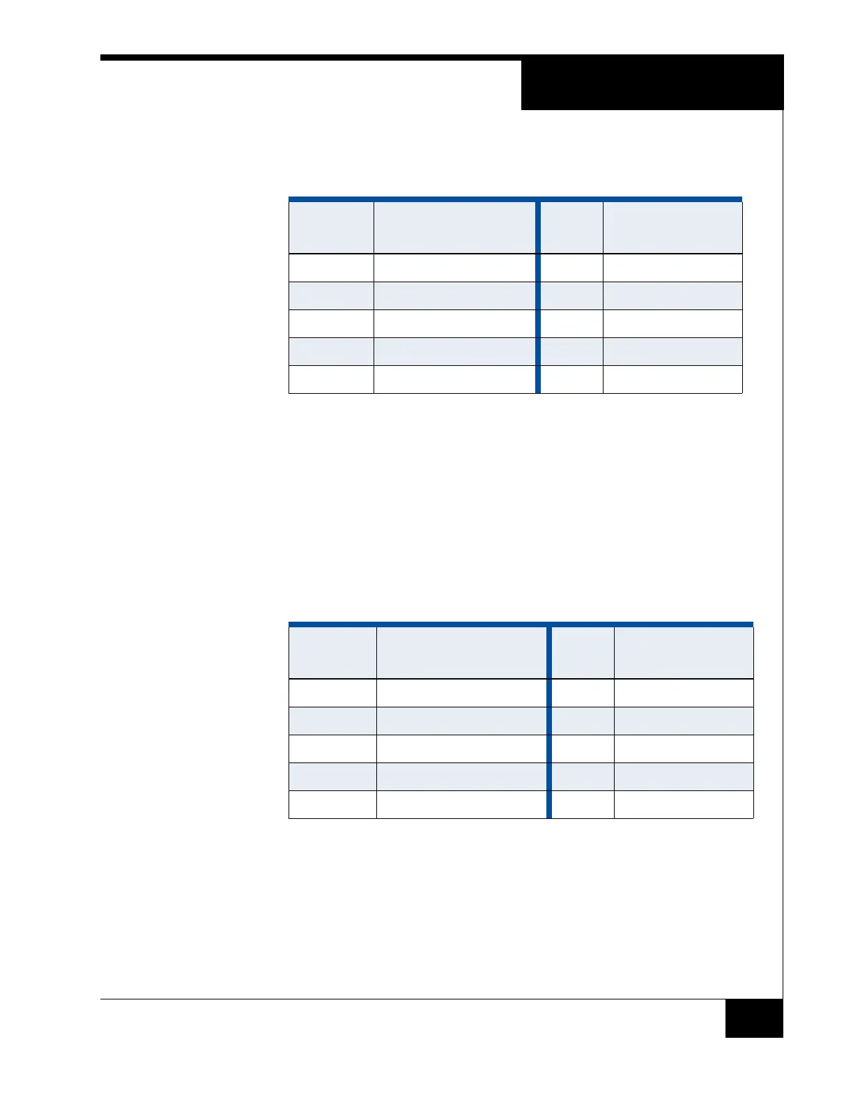
TABLE 2. DB25-to-P6 Pin Connections
Modem
DB25 Pin
Modem DB25 Signal
iSTAR
P6 Pin
iSTAR P6 Signal
2Tx1Tx
4 RTS 2 RTS
5 CTS 3 CTS
3 Rx 4 Rx
7 GND 5 GND
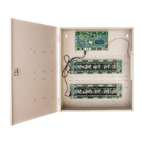
TABLE 3. DB9-to-P6 Pin Connections
COM Port
DB9 Pin
COM Port DB9 Signal
iSTAR
P6 Pin
iSTAR P6 Signal
2Rx1Tx
8 CTS 2 RTS
7 and 1 RTS and CD 3 CTS
3 Tx 4 Rx
5 GND 5 GND