GCM General Control Module
6
GCM GENERAL
CONTROL MODULE
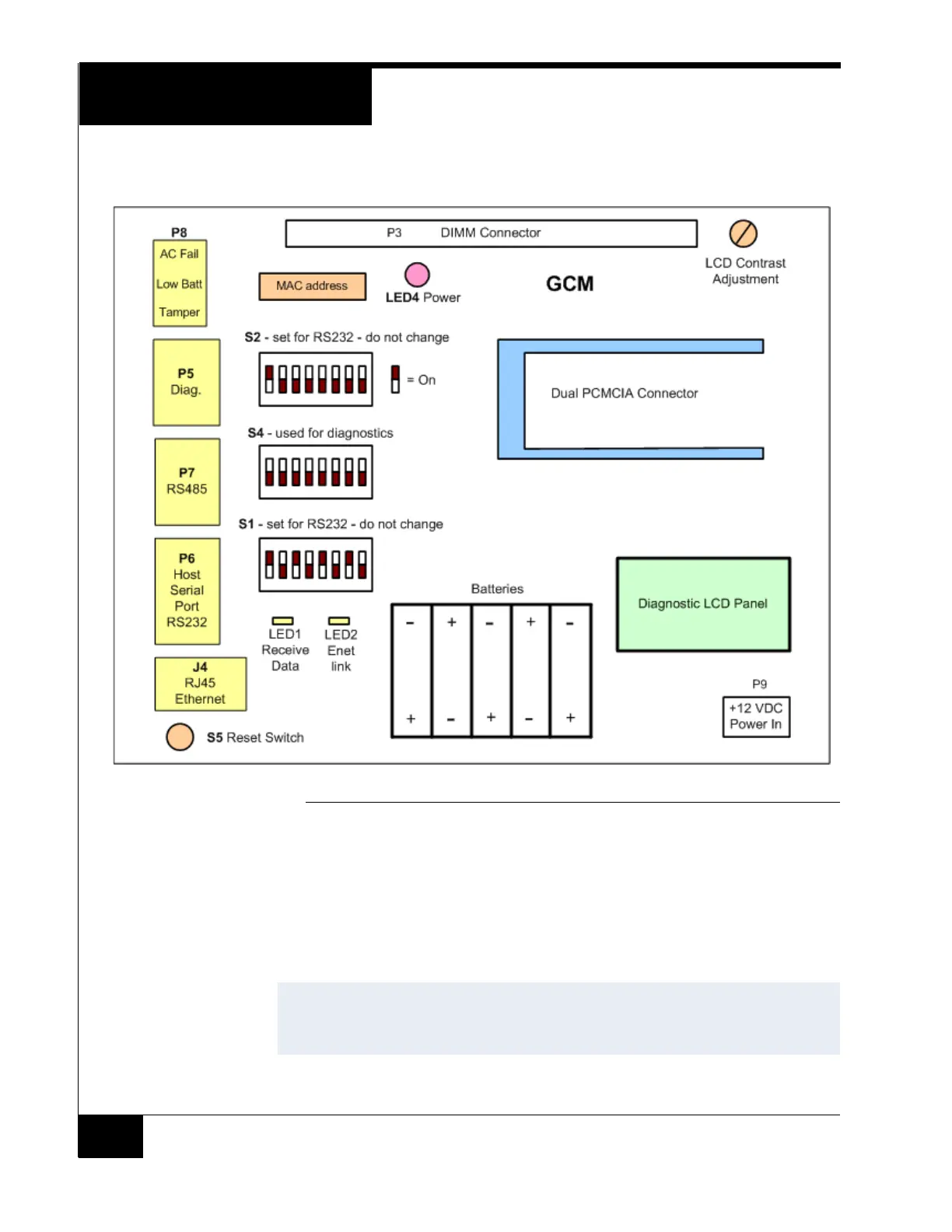
Figure 4 shows the GCM components described in this guide.
FIGURE 4. CGM Control Module Layout
Network Connection
Connect a CAT 5 RJ45 cable to J4. If the other end of the cable is connected to a hub or
switch, it must be straight through. If it is connected directly to a NIC card on the server,
it must be a crossover.
LED2 indicates the Ethernet Link signal and LED1 displays the Receive Data signal.
NOTE
This document applies to both C•CURE® 800 and C•CURE® 9000 iSTAR Pro
controllers, unless noted otherwise. Version 1.0 of C•CURE 9000 does not
support multiple controller clusters, serial ports, or RAS connections.