RM2L-NH Setup
10
Grounding and
Shielding
Single RM2L-NH Keypad
1. When connecting a single RM2L-NH Keypad to the bus, use twisted pair, shielded
minimum 24 AWG cable. Attach the shield at one end only, usually at the apC or
iSTAR end.
2. Attach a local earth ground (18 or 22 gauge) wire to the J5 component on the RM
module of the RM2L-4000 keypad.
Multiple RM Bus Devices
When wiring an RM2L-NH Keypad to a bus with multiple devices, such as other
RM readers, I/8s, or R/8s:
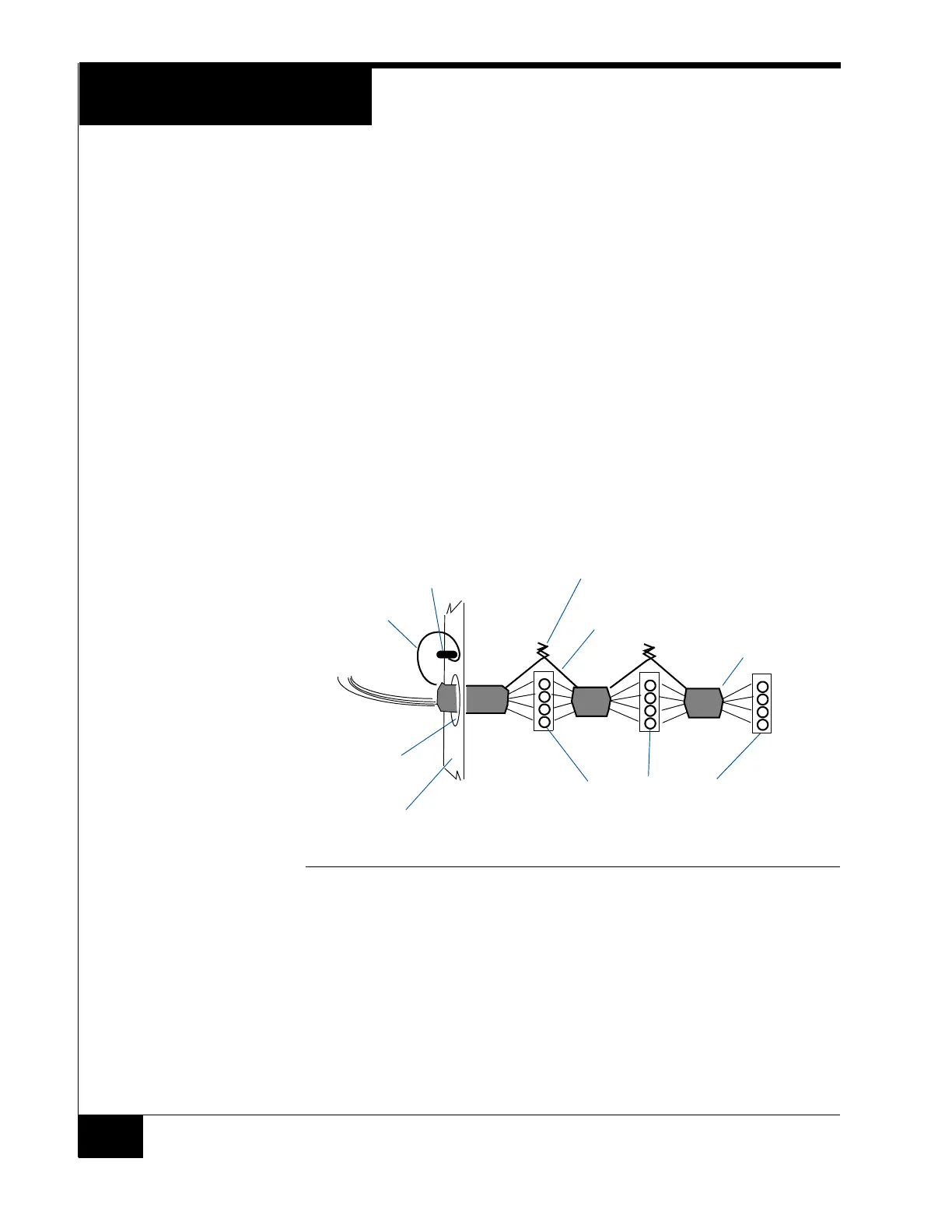
1. Attach the shields along the bus together (insulate each connection). Snip off the
shield wire at the end of the bus. See Figure 7
2. Attach the shield to the ground at only one point – at the ground stud inside the
iSTAR or apC cabinet adjacent to the knockout.
3. Attach a local earth ground (18 or 22 gauge) wire to the J5 component on the
RM2L-NH keypad.
FIGURE 7. RM Shield Wiring
Setting Module
Address and
EOL Termination
To set the module address, set SW1 (16 position rotary switch) to a number from one to
eight. Every RM2L-NH device on a bus must have a unique address.
To set RS-485 EOL (End of Line) termination, set SW3-5 to the On (closed) position if
the module is the last unit on the bus. If the module is not the last unit on the bus,
SW3-5 should be Off (open).
ACM module
RS-485 connector on a reader
Knockout
Twist shield wires together and insulate
(do not ground)
Ground stud
(bus configuration)
Shield wire
Enclosure/cabinet
Shield wire
Snip off shield
wire at end of
bus