Installation
6
Wiring the Inputs,
Outputs, Reader Bus
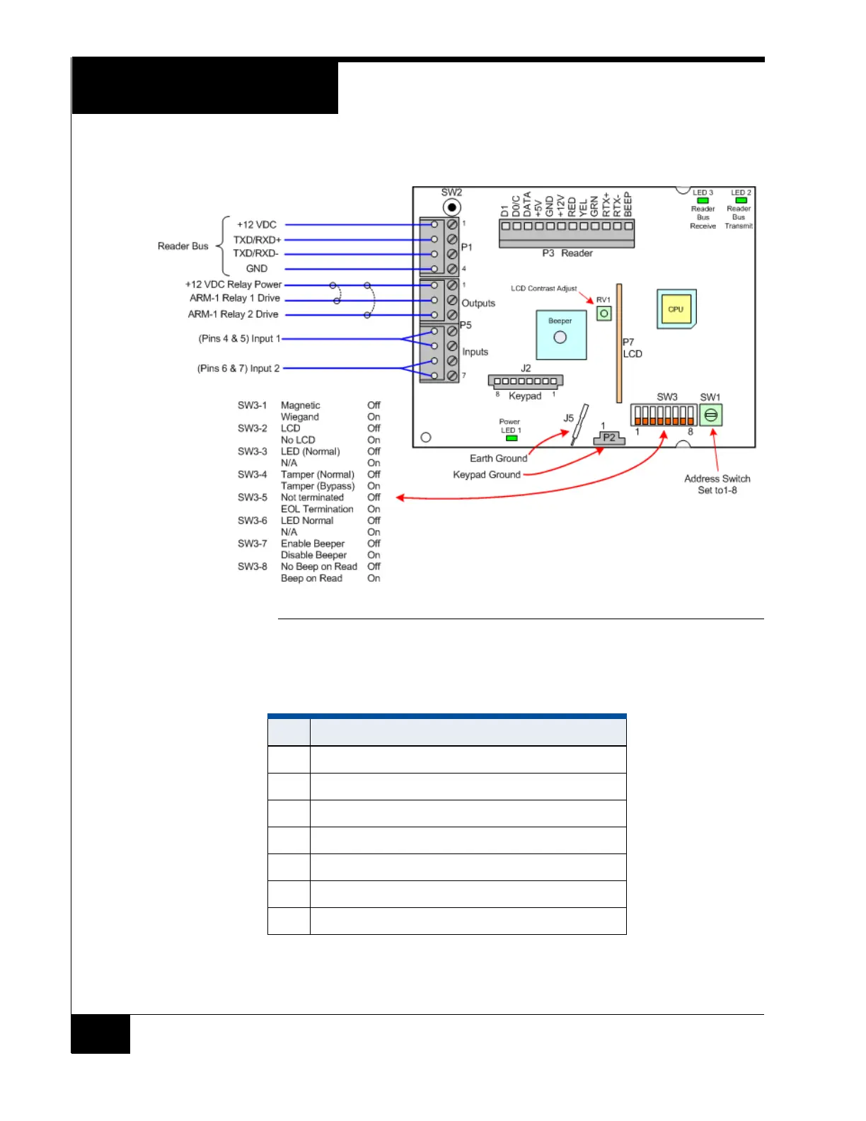
Figure 5 shows RM-4 P1 and P5 wiring.
FIGURE 5. RM-4 Wiring Requirements
NOTE:
Set SW3-2 to OFF for UL installations.
TABLE 2. P5 Input and Output Wiring
P5 Function
1 +12 VDC relay power
2 Relay 1 drive (GND) for first ARM-1 Module
3 Relay 2 drive (GND) for second ARM-1 Module
4 Supervised Input1
5 Supervised Input1
6 Supervised Input2
7 Supervised Input2