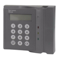
RM2L-NH Setup
7
RM2L-NH SETUP
To set up an RM2L-NH Keypad Arming Station:
1. Set the Device Address Switch, SW1 (a 16 position rotary switch, see Figure 5), to a
number from one to eight. Each Device along the bus must have a unique address.
2. The SW3-2, SW3-3, and SW3-6 Configuration Switches are factory preset to OFF
for the RM2L-NH Device.
3. SW3-1, SW3-7, and SW3-8 are not used.
Note that you can set SW3-4 and SW3-5 as required.
Caution: To properly terminate an RS-485 line, only the last unit on the bus
should have SW3-5 in the On (closed) position.
NOTE:
Set SW3-2 to OFF for UL installations.
4. Connect P5 input and output wiring, as shown in Table 2 and Figure 8 on page 11.
TABLE 3. SW3 Configuration Switch Settings
SW3 # Function Off (Open) On (Closed)
SW3-1 Device type (N/A) Magnetic (N/A) Wiegand (N/A)
SW3-2 LCD LCD Present No LCD
SW3-3 LED Option Normal N/A
SW3-4 Tamper Normal Bypass
SW3-5 (see
caution below)
EOL-Termination Not last unit Last unit in bus
SW3-6 LED Option Normal N/A
SW3-7 Beeper Control (NA) Enable RM-4
Beeper (NA)
Disable RM-4 Beeper
(NA)
SW3-8 Beep on Read Control
(N/A)
No Beep on Read
(N/A)
Enable Beep on Read
(N/A)