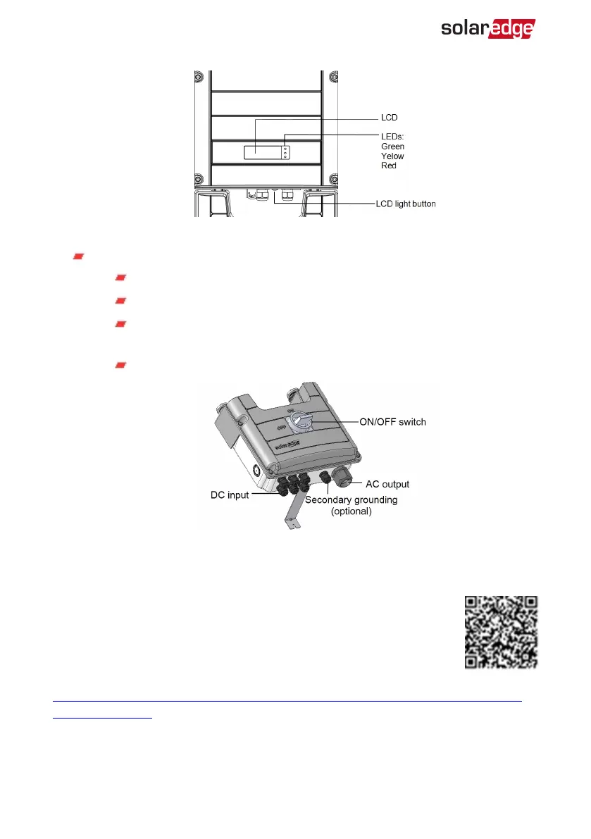
Figure 6: Inverter front view
DC Safety Unit (if applicable), including:
ON/OFF switch: connects and disconnects the DC power of the system
AC output: Cable gland for connection to the grid
DC input: Cable glands or MC4 connectors for connection of the PV
installation
Secondary grounding (optional): Cable gland for grounding
Figure 7: DC Safety Unit
Mounting the Inverter
The inverter is typically mounted vertically, and the instructions in this
section are applicable for vertical installation. Some three phase inverter
models can be installed horizontally (above 10° tilt) as well as vertically,
and at any tilt over 10° up to 90°. For information and instructions for
horizontal mounting refer to
http://www.solaredge.com/sites/default/files/application_note_horizontal_mounting_of_three_
phase_inverters.pdf.
The inverter is supplied with a mounting bracket.
-Three Phase System Installation Guide MAN-01-00057-4.1
26 Mounting the Inverter