DC cable
AC cable
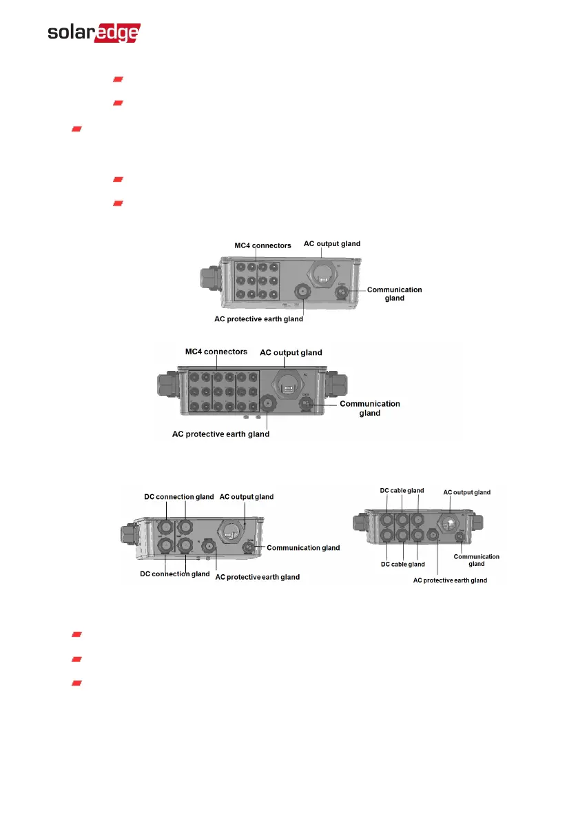
DC input: MC4 connectors / cable glands: for DC+/- connection of the PV
installation, there are 3 glands / 6 MC4 connectors for each unit.
Each gland has 3 openings to support three strings:
each opening can support 5-8.8 mm PV cable outer diameter
each terminal block in the connection unit can support 4-10mm
2
PV
wire cross section
Figure 10: Connection Unit with MC4 Connectors bottom interface
for 1 Secondary Unit (left), for 2 Secondary Units (right)
Figure 11: Connection Unit with glands bottom interface
for 1 Secondary Unit (left), for 2 Secondary Units (right)
AC output: cable gland for connection to the grid, M50 20-38mm diameter
AC protective earth gland: cable gland for grounding , 9-16 mm diameter
Communication gland: for connection of communication options. Refer to
Setting Up Communication
on page 61.
Chapter 3: Installing the Primary and Secondary Unit(s) 27
Three Phase Inverter with Synergy Technology Installation MAN-01-00402-1.2