4. Lift the device from the sides, or hold it at the top and bottom to lift the device into
place.
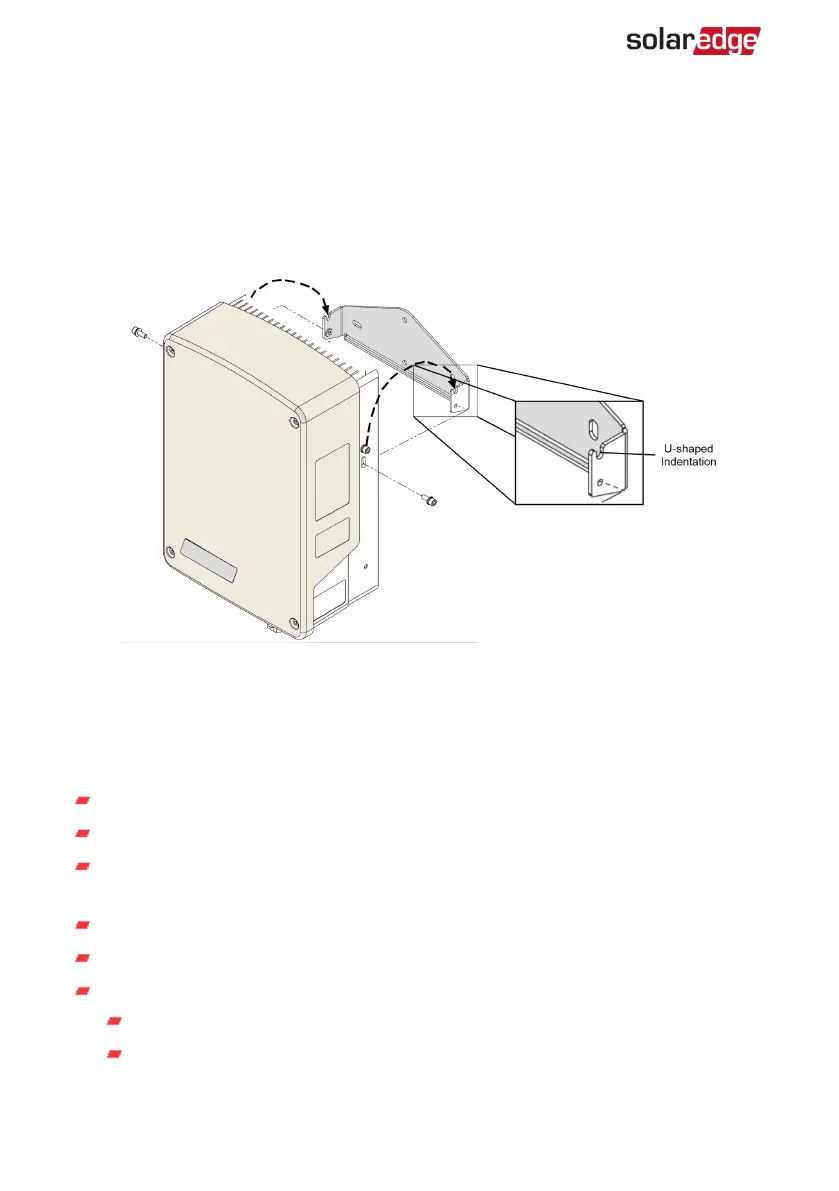
5. Lower the device onto the U-shaped indentations (see
Figure 7
). Let the device lay
flat against the wall or pole.
6.
Insert the two supplied screws through the outer heat sink fin on both sides of the
device and into the bracket. Tighten the screws with a torque of 4.0 N*m / 2.9 lb.*ft.
Figure 7: Hanging the device on the bracket
Connection
Guidelines
Make sure that power is disconnected from the main distribution panel.
Connect the device through a circuit breaker in the AC distribution panel.
Connect the device through a 2-pole magneto-thermal switch breaker in the AC
distribution panel.
Use a 3-core cable with a minimum wire cross section of 2.5 mm
2
.
Use the connection gland suitable for the cable diameter (6 - 12 mm or 4 - 8mm).
Use the following cable types for power supply:
Rubber sheathed, H05RR-F of type HD 22.4
PVC sheathed, H05W-F of type HD 21.5
Smart Energy Hot Water Installation Guide MAN-01-00570-1.4
14 Connection
 Loading...