Chapter 3 Operation Control
3.1 Panel Layout and Instruction
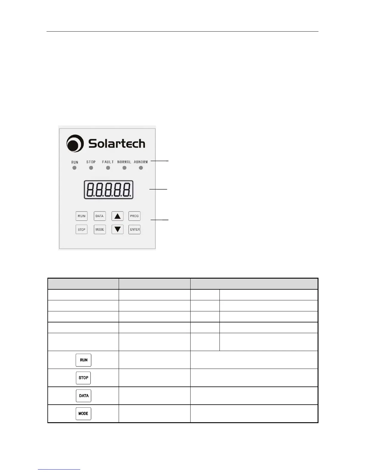
Solar DC pumping controller uses LED display operation panel which is shown as
the figure below, it includes 5 LED lights and 5-digit 8-SEG nixie tubes and 8 keys in
2 rows.
Mode indicator lights:
RUN, STOP, FAULT, NORMAL,ABNORM (AL)
5-digit nixie tube display
Operation keys
Fig. 3-1 Keyboard layout and name of each part
Indicator Light & Key Name Function Description
RUN Running indicator light Green Bright: Controller is running
STOP Stopping indicator light Red Bright: Controller is stopped
FAULT Fault indicator light Red Bright: System fault
NORMAL Normal indicator light Green Bright: System normal
ABNORM Abnormal indicator light Red
Bright: Water level in tank or well is
abnormal
Run key Control the start of the controller.
Stop key Control the stop of the controller.
Data inquiry key Not being used.
Mode switch key
1.