19.01-16
SolaStat-Plus Sensor Maintenance.
Lengthening SolaStat-Plus Sensor Wire.
The sensor wire can be lengthened within certain guidelines. Poor connections or induced
interference can cause false temperature readings.
1. The sensor is not polarized- it can be connected either way around.
2. The wire normally used for sensor lengthening is twin 0.5mm
^2
stranded speaker wire.
3. Firmly attach wires to each other by either soldering (heatshrink over each joint) or by quality
screw terminals. Joins must be kept dry.
4. It is recommended that sensor leads be kept 300mm away from mains and comms cables.
5. Over 20 metres; extra care must be taken to avoid electrical interference being picked up.
6. In ‘noisier’ electrical environments screened cable may be required.
7. The absolute maximum cable length is 100 metres.
Replacing a SolaStat-Plus Sensor.
If a damaged sensor needs to be replaced then the cover of the enclosure will need to be opened
unless the choice is made to join the wires externally (see “Sensor Wire Lengthening” section).
1. Remove the mains power supply, preferably remove the plug from the wall socket. Make
sure no other power source is feeding back through other connections.
2. Remove the 4 screw covers on each corner of the lid of the enclosure. This will require a fine
tipped tool such as a screw driver. Be careful not to damage the lid. Always press the tool
away from you to avoid injury if you slip.
3. Remove the 4 screws that hold the lid on.
4. Unscrew the damaged sensor from the terminal block.
5. Loosen the cable clamp for the sensor leads.
6. Carefully pull the wire back through the opening in the bottom case.
7. Thread the new sensor wire back through where the old one came from.
8. Place the wires of the new sensor into the terminal block where the old sensor came from
and retighten the screws.
9. Do not allow the sensor cables to come within 10mm of the high voltage connectors or
components inside the enclosure. Tighten the screws on the cable clamp.
10. Replace the lid, replace the 4 screws and tighten.
11. Push in 4 new screw covers available from your distributor or ICM Ltd. Note: there are
locating lugs to ensure correct orientation.
12. Reconnect the SolaStat-Plus and turn on the power.
13. Check sensor is reading correctly and check SolaStat-Plus operation as per “What You Should
See” section of this manual.
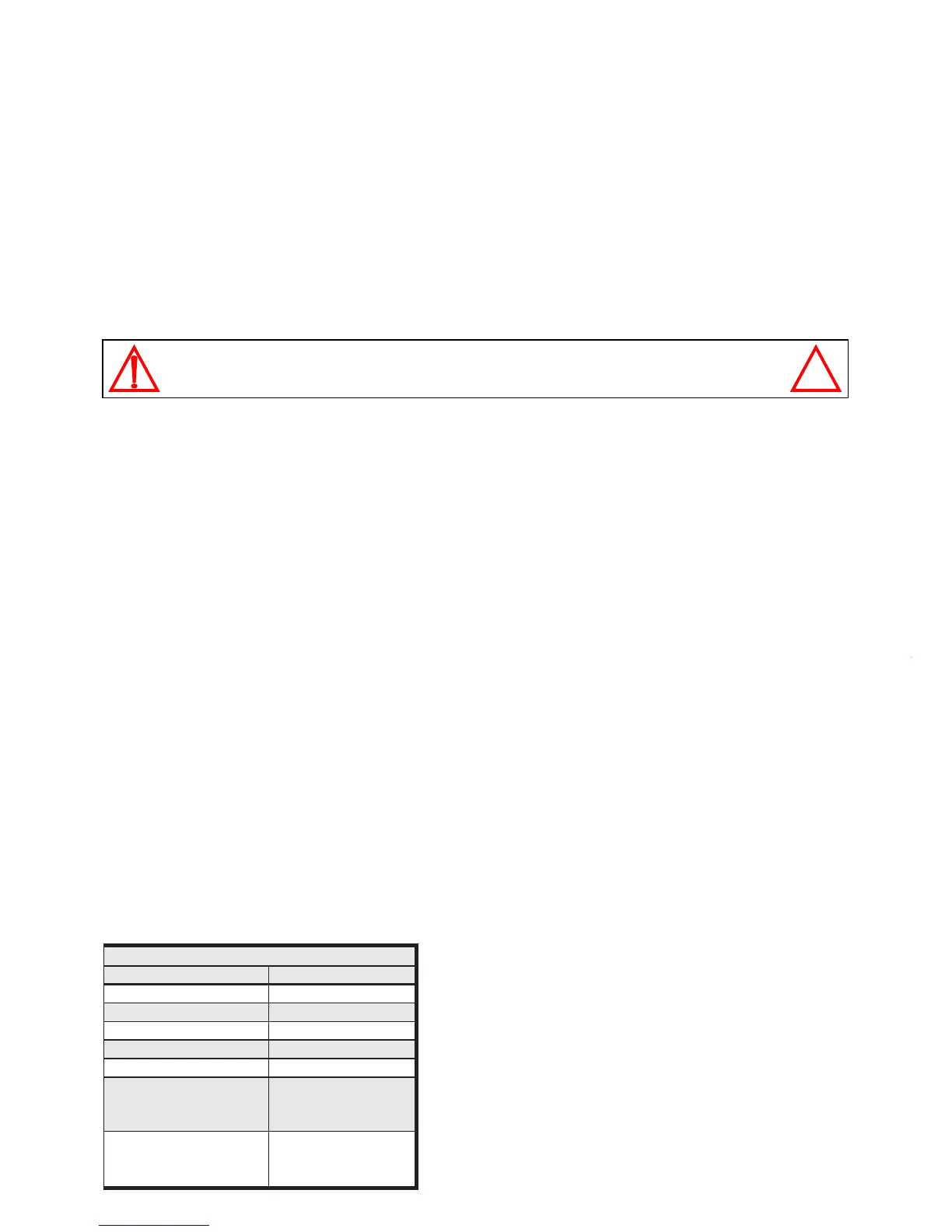
The table below has the correct resistance values of the sensor at different temperatures. The
sensor must be removed from the SolaStat-Plus to measure these values correctly. Follow the
above procedure for removal of the sensor.
CAUTION: Dangerous Voltages may be present. The SolaStat has no user serviceable parts.
Protective enclosure only to be opened by qualified personnel.
Remove ALL power sources before removing protective cover.
secnatsiseRrosneS
erutarepmeT kniecnatsiseR WW
W
WW
Cº052.72
Cº52 00.01
Cº05261.4
Cº57 529.1
Cº001379.0
.'trohs'roC051evobA
yalpsiDno'dSS'
nOthgiLrosneS
003.0<
.'nepo'roC04-woleB
yalpsiDno'dSS'
gnihsalFthgiLrosneS
002>
A ‘short’ circuit can be caused by the sensor wires being
connected together. Check the wires are not partially
cut. (eg Sharp roofing iron.) or moisture is not getting
into the sensor causing corrosion.
An ‘open’ circuit can be caused by the sensor wires
being broken. Check the wires are not cut. (eg Sharp
roofing iron.) or moisture is not getting into the sensor
causing corrosion.