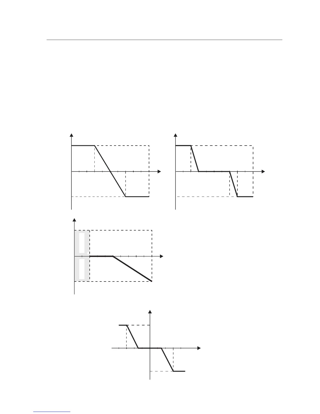
Reactive power control, Reactive standard curve cos φ = f(P)
0.50.2 1.0
0.95
0.95
cosφ
capactive
inductive
f (P)
curve C
For VDE ARN 4105, curve cos φ = f(P) should refer to curve A. default values of setting are as
shown in curve A.
For E 8001, curve cos φ = f(P) should refer to curve B. default values of setting are as shown
in curve B.
For CEI 0-21, default value of PFLockInPoint is 1.05, when Vac > 1.05Vn, and Pac> 0.2 Pn,
curve cos φ = f(P) should refer to curve C. Default value of PFLockOutPoint is 0.98, when Vac
< 0.98 Vn, cos φ = f(P) will exit curve C.
Reactive power control, Reactive standard curve Q= f(V)
Q
V
Qmax
-Qmax
V2sV1s
V1iV2i
V2i=0.90Vn
V2s=1.10Vn
V1s=1.08Vn=QuVlowRate
V2i=0.92Vn=QuVlowRate
0.9
0.9
Upper limit
capactive
inductive
f (P)
Lower limit
Power Lower
Power Upper
curve A
0.3
0.7
0.9
0.9
Upper limit
capactive
inductive
f (P)
Lower limit
Power Lower
Power Upper
curve B
0.3
0.7
0.2
0.8
Operation Method
44
 Loading...