1
2
3
4
1
2
3
4
1
2
3
4
1
2
3
4
1
2
3
4
1
2
3
4
1
2
3
4
1
2
3
4
1
2
3
4
6. Operation
6.1 Indicator Pannel
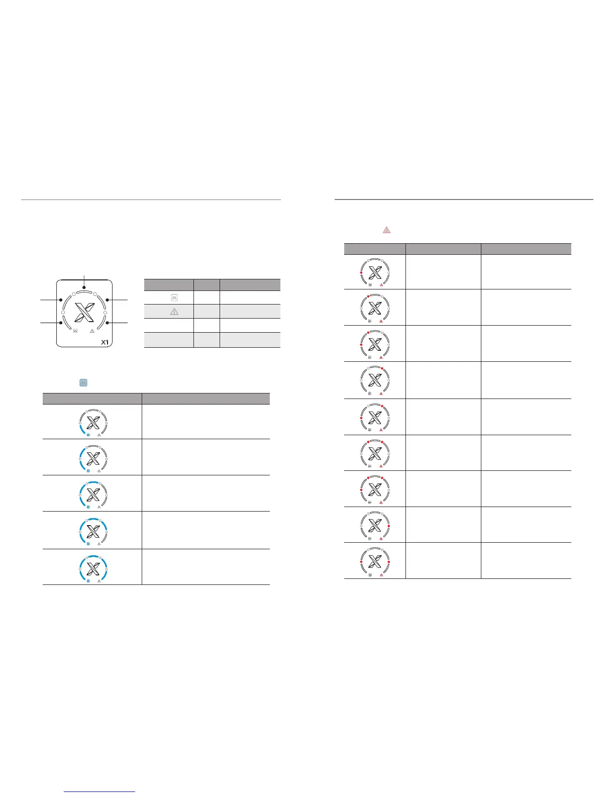
6.2 Indicator Information
Make sure the inverter is intact during transportation. If there are some visible
damages, such as cracks, please contact your dealer immediately.
6. Operation6. Operation
1
a
L1
L2 L4
L3
L5
b
2
3
4
Output power range : 0% ~ 20%
PV Volt Fault PV Over Voltage Fault
Isolation Fault Isolation Fault
Temp Over Fault Over Temperature Fault
DCI Fault
RCD Fault
Mains Lost
Grid Volt Fault
Grid Freq Fault Grid Freq Fault
Consistant Fault
Output power range : 20% ~ 40%
Output power range : 40% ~ 60%
Output power range : 60% ~ 80%
Output power range : 80% ~ 100%
Blue light “a” keeps on. Light “a,b,c,d” are unlit:
Red light “b” keeps on, light “L1, L2, L3, L4, L5” are unlit :
Indicator
Indicator
Description
Fault Description
Indicator light
a
blue
working properly
fault
fault types
output power
blue
red
red
b
1/2/3/4
L1/L2/L3/L4/L5
Color Description
1
2
3
4
1
2
3
4
1
2
3
4
1
2
3
4
1
2
3
4
Normal working
Working fault
DCI Device Fault
DCI OCP Fault
RCD Fault
Grid Lost Fault
Sample Fault
Grid Volt Fault
2524

 Loading...