32
Operation MethodOperation Method
•1 level
a) The first line displays the parameters(Power, Today and Total) and the values.
b) The second line shows the running status.
Namely, “Power” means the timely output power;
“Pgrid” means the power export to or import from the grid; (Positive value means
the energy feeds into grid, negative value means the energy used from the grid)
“Today” means the power generated within the day.
“Normal” means the status of the inverter.
•2 level
Long press any first-level parameter can enter the sencond-level “Status”
parameter interface.
The user can also see other parameters, such as the Language( without password ),
Setting ( need password ), Meter energy, Error Logs of the inverter, and About ( the
user can watch the information of the inverter).
•3 level
Long press the sencond-level parameter can enter the corresponding third-level
parameter interface.
a) Status: The user can see the U/I/P parameters of the grid and the PV, such as the
Ugrid, Igrid, P and F of the grid, and the Usolar, Isolar and Psolar of the PV.
b) Language: This inverter provides several languages for customer to choose.
c) Setting: Entering the installer password, the information of the LCD interface is
as the previous page shown.
(1) Safety: The user can set the right safety standard here.
(2) Grid: Usually end user do not need to set the grid parameters. All default value
have been set before leaving factory according to safety rules.
If need to reset, any changes should according to the requirement of local grid.
LCD Display
Ø
Parameter Comment
Normally
Vac upper
Voltage high protect
Vac lower Voltage low protect
Vac upper slow Voltage high slow protect
Vac lower slow Voltage low slow protect
Fac upper Frequency high protect
Fac lower
Frequency low protect
Fac upper slow Frequency high slow protect
Fac lower slow Frequency low slow protect
Vac 10m avg 10 min voltage high protect
Apply to EN50438_NL.
FreqSetPoint
FreqDropRate
Frequency set point
Frequency droop rate
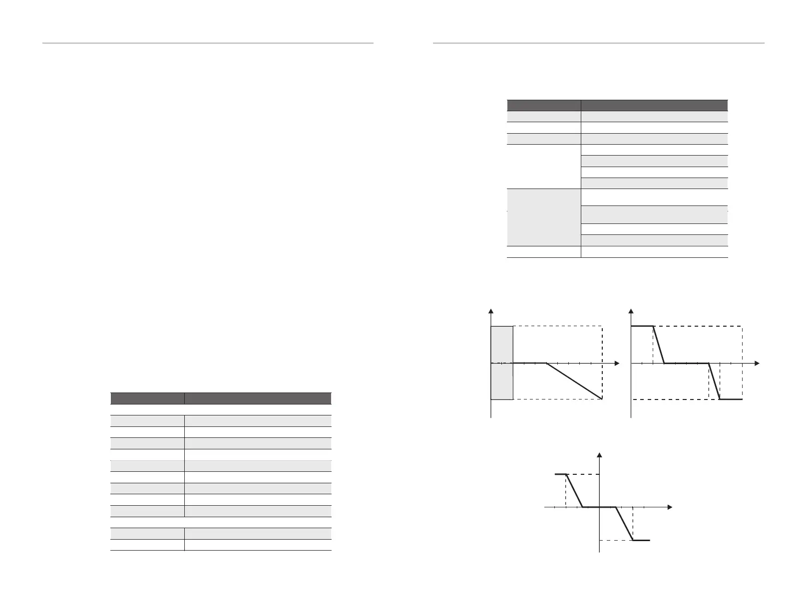
For VDE ARN 4105, curve cos φ = f(P) should refer to curve A. default values of setting are as
shown in curve A.
For E 8001, curve cos φ = f(P) should refer to curve B. default values of setting are as shown in
curve B.
Reactive power control, Reactive standard curve Q= f(V)
Q
V
Qmax
-Qmax
V2sV1s
V1iV2i
V2i=0.90Vn
V2s=1.10Vn
V1s=1.08Vn=QuVlowRate
V2i=0.92Vn=QuVlowRate
Mode Comment
Off
Under-Excited PF value
Over-Excited PF value
PF(p)
Upper limit
Lower limit
Power Upper
Power Lower
Q( u )
QuVupRate
QuVlowRate
-
( EN50549_NL )
( EN50549_NL )
Fixed Q Power
Q Power( for some local grids )
QUrangeV1 ( AS4777.2 )
QUrangeV4 ( AS4777.2 )
(3) Power Factor: ( For specic country if required by the local grid.)
There are 6 modes for selecting: Off , Under-Excited, Over-Excited, PF(p), Q( u ).
All parameters are shown below.
33
0.9
0.9
Upper limit
capactive
inductive
f (P)
Lower limit
Power Lower
Power Upper
curve B
0.3
0.7
0.2
0.8
0.9/0.95*
0.9/0.95*
leading
p/p
lagging
curve A
0.5 1.0
over-excited
under-excited
0.2
1
Emax
cos φ

 Loading...