03
02
1 Notes on this Manual
1.2 Target Group
This manual is for qualied electricians.The tasks described in this
manual only can be performed by qualied electricians.
1.3 Symbols Used
Danger!
“Danger" refers to a dangerous situation that, if not
avoided, will result in a high level of risk such as serious
injury or even death.
Warning!
“Warning” indicates a hazardous situation which, if not
avoided, could result in death or serious injury.
Caution!
“Caution” indicates a hazardous situation which, if not
avoided, could result in minor or moderate injury.
Note!
“Note” provides tips that are valuable for the optimal
operation of our product.
1.1 Scope of Validity
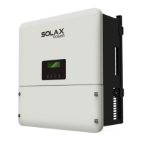
X1-Hybrid-3.0-D
X1-Hybrid-3.0-M
X1-Hybrid-3.7-D
X1-Hybrid-3.7-M
X1-Hybrid-5.0-D
X1-Hybrid-5.0-M
X1-Hybrid-6.0-D
X1-Hybrid-6.0-M
Note:”X1-Hybrid G4"Series refers to the energy storage inverter
that supports photovoltaic grid-connected.
“5.0"means 5.0kW.
“D”means with “DC Switch” ,“M”means externally attached
X1-Matebox for full load off-grid operation.
Keep this manual available at any time.
X1-Hybrid-7.5-D
X1-Hybrid-7.5-M
5 Electrical Connections...........................................................31
.........................................................................................
5.2 Grid Port and Off-grid Output Connection.......................
5.3 Off-grid Block Diagram......................................................................
..............................................................................5.4 Battery Connection
5.5 Communication Connection.......................................................
5.5.1 Introduction to DRM Communication.....................................
5.5.2 Introduction to Meter/C T Communication...........................
5.5.3 COM Communication......................................................................
5.5.4 Communication Connection Steps...........................................
5.6 Grounding (mandatory)....................................................................
5.7 Monitoring Connection....................................................................
5.8 Check All Below Steps Before Starting Inverter...............................
5.9 Inverter Operation.................................................................................
6 Firmware upgrading...........................................................................................65
7 Setting........................................................................................69
7.1 Control Panel................................................................................
7.2 Menu Structure...........................................................................
7.3 LCD Operation...........................................................................................
8 Troubleshooting...............................................................95
8.1 Trouble Shooting....................................................................95
8.2 Routine Maintenance.............................................................101
9 Decommissioning 102
10 Disclaimer 103
5.1 PV Connection
31
35
36
44
48
49
52
53
54
59
61
63
64
69
70
71
102
102
102
102
9.1 Dismantling the Inverter
9.2 Packaging
9.3 Storage and Transportation
9.4 Waste Disposal
.................................................................
......................................................................................................
..................................................................
........................................................................................
....................................................................
........................................................................................
The following types of safety instructions and general information
appear in this document as described below:

 Loading...


