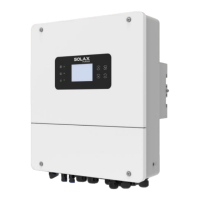
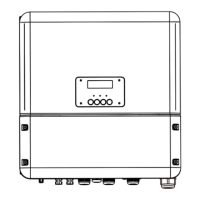
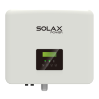
What should I do if my SolaX Power X1-Hybrid-LV displays 'Low soc of grid-connected battery'?
- AAshley JohnsonSep 4, 2025
If your SolaX Power Inverter displays 'Low soc of grid-connected battery', stop discharging and start charging.

What should I do if my SolaX Power X1-Hybrid-LV displays 'Low soc of grid-connected battery'?
If your SolaX Power Inverter displays 'Low soc of grid-connected battery', stop discharging and start charging.
What should I do if my SolaX Power X1-Hybrid-LV displays 'Arc fault'?
If your SolaX Power Inverter is showing an 'Arc fault' message, wait for a while and observe if it returns to normal operation.
What to do if my SolaX Power X1-Hybrid-LV Inverter displays 'PV connection configuration error'?
If your SolaX Power Inverter shows a 'PV connection configuration error', turn off the PV, battery, and power grid. Then, restart the inverter and confirm whether the PV connection is correct.
What should I do if my SolaX Power X1-Hybrid-LV displays 'BuckBst startup failed'?
If your SolaX Power Inverter displays 'BuckBst startup failed', wait for a while to see if it returns to normal.
What to do if my SolaX Power X1-Hybrid-LV Inverter shows 'Meter loss'?
If your SolaX Power Inverter displays 'Meter loss', please check if the meter is connected or if the meter communication line works normally.
What should I do if my SolaX Power Inverter displays 'BST2 hardware overcurrent'?
If your SolaX Power Inverter displays 'BST2 hardware overcurrent', wait for a while to see if it returns to normal.
What should I do if my SolaX Power X1-Hybrid-LV displays 'The grid voltage exceeds the allowable value 2'?
If your SolaX Power Inverter displays 'The grid voltage exceeds the allowable value 2', check whether the grid voltage is within the normal working range.
What should I do if my SolaX Power X1-Hybrid-LV Inverter displays 'External fan failure.'?
If your SolaX Power Inverter displays 'External fan failure', please check if the external fan is damaged or blocked.
What should I do if my SolaX Power X1-Hybrid-LV displays 'Inverter relay fault'?
If your SolaX Power Inverter displays 'Inverter relay fault', wait for a while to see if it returns to normal.
What to do if my SolaX Power Inverter displays 'Battery type configuration error'?
If your SolaX Power Inverter displays 'Battery type configuration error', turn off the PV, battery, and power grid, restart the inverter, and confirm whether the battery type is correct.
| Model | X1-Hybrid-LV |
|---|---|
| Rated Grid Voltage | 230 V |
| Grid Frequency | 50Hz / 60Hz |
| Max. PV Input Voltage | 600 V |
| Number of MPP Trackers | 2 |
| Max. Battery Charge/Discharge Current | 100 A |
| Max Efficiency | 97.6% |
| Weight | 25 kg |
| Operating Temperature Range | -25 °C to 60 °C |
| Cooling Method | Natural convection |
| Protection Degree | IP65 |
| AC Output Rated Power | 3000W / 3680W / 5000W |
| Max. PV Input Power | 6 kW |
| Battery Voltage Range | 40 V - 60 V |
| Communication | WiFi |
| Max. DC Power | 6 kW |
| Max. Charging Power | 3.0 kW / 3.6 kW / 4.6 kW / 5.0 kW |
| Max. Discharging Power | 3.0 kW / 3.6 kW / 4.6 kW / 5.0 kW |
| Max. AC Output Power | 3.3 kW / 4.0 kW / 5.0 kW / 5.5 kW |
Provides information on the proper installation, commissioning, maintenance and troubleshooting for the inverter.
This manual is for qualified electricians; tasks can only be performed by them.
Explains the safety instructions and general information symbols used in the document.
Covers critical safety warnings regarding high voltages, hot surfaces, radiation, grounding, and electrical shock.
Details the necessity and type of surge protection devices for PV systems to prevent lightning damage.
Explains symbols found on the inverter and its type label for clarity and safety.
Defines symbols indicating inverter status like operation, battery, and errors.
Explains certification marks (CE, UKCA, TUV) and safety symbols on the inverter's label.
Outlines European low voltage regulations, safety instructions, and system licensing conditions for inverter compliance.
Provides essential safety guidelines for using batteries with the inverter, referring to specific data.
Highlights the inverter's capabilities as a high-quality solar, charger, and EPS unit with IP65 protection.
Illustrates the inverter's EPS wiring schemes and connection options for various loads.
Details the inverter's operational modes like Self Consumption, Surplus FIT, and Backup for different scenarios.
Optimizes self-consumption by managing battery charge/discharge based on PV and load power.
Allows feeding surplus electricity to the grid when electricity prices are high and subsidies are low.
Suitable for high Internet subsidies; feeds surplus PV power to the grid.
Prioritizes feeding PV power to the grid, with battery charging only when PV power exceeds inverter rating.
Manages power consumption during normal grid conditions to reduce peak demand or fill valleys.
Enables the inverter to function as UPS or EPS, supplying power during grid outages.
Manages solar power for loads and battery charging, with grid feeding enabled under specific conditions.
Manages solar power for loads and battery charging; grid feeding is enabled or limited based on conditions.
Handles solar and utility power for loads and battery charging when solar availability is limited.
Presents the physical dimensions of the inverter with clear diagrams for reference.
Identifies and describes the various connection ports on the inverter for proper wiring.
Provides specifications for the DC input parameters of the inverter models, including voltage and current.
Details the AC input and output specifications, covering current, power, voltage, and frequency.
Specifies the output parameters for the Emergency Power Supply (EPS) function, including power and current.
Lists battery-related specifications such as voltage, charging current, and strategy for different battery types.
Presents system-wide efficiency data, including MPPT, maximum, and Euro efficiency.
Details the built-in protection features of the inverter, such as anti-islanding and over-voltage protection.
Specifies power consumption, operating temperatures, humidity, storage conditions, and noise levels.
Includes general specifications like dimensions, weight, cooling concept, topology, and communication interfaces.
Instructions on how to inspect the inverter for damage after delivery and report issues.
Lists the components and accessories included in the inverter package for verification.
Details crucial precautions for safe and proper installation, including environmental and site conditions.
Lists the necessary tools and additionally required materials for installing the inverter.
Specifies requirements for the installation environment, carrier, angle, and space for optimal performance.
Provides step-by-step instructions for physically mounting the inverter bracket and the inverter.
Describes how to connect photovoltaic modules to the inverter, including wiring methods and requirements.
Explains connections to the grid, generator (GEN), and EPS output, including breaker recommendations.
Details requirements for loads connected to the EPS output, focusing on power ratings and inrush current.
Outlines requirements and steps for connecting low voltage lithium and lead acid batteries, including safety breaker.
Covers general requirements for connecting batteries, including breaker selection and type.
Mandates installing a non-polar DC MCB for safety before battery connection.
Explains how to connect the battery temperature sensor for accurate monitoring.
Details the various communication ports and their definitions for connecting external devices.
Defines the function of each communication port, such as DRM, COM, BMS, and Meter/CT.
Details how to connect CTs or electric meters for monitoring household electricity usage.
Explains connections for BMS, DRM, and COM ports, including pin definitions and steps.
Provides the pinout and function of the BMS communication port for battery management.
Defines the DRM port for external control signals, compliant with AS4777 regulatory requirements.
Describes the COM port for customization, monitoring, and external equipment control.
Details how to connect multiple inverters in parallel for increased capacity and system redundancy.
Explains how to connect external devices like generators using the dry-contact output ports.
Details the mandatory steps for grounding the inverter to prevent electric shock and ensure safety.
Describes how to connect accessories for inverter monitoring via WiFi, LAN, or 4G dongles.
Provides a crucial checklist of all connection and safety steps before powering on the inverter.
Guides on how to safely start and operate the inverter, including turning on breakers and switches.
Steps to prepare for firmware upgrade, including U disk size, format, and file acquisition.
Procedure for plugging in the U disk, initiating the upgrade, and verifying success via indicator lights.
Explains the inverter's control panel layout, including the LCD screen and navigation buttons.
Details the hierarchical structure of the inverter's menu system for accessing various settings.
Guides on how to navigate and interact with the inverter's LCD screen for settings and information.
Describes how to access and navigate the main menu for changing settings or obtaining information.
Details the default interface displayed on the inverter's LCD screen, showing key operational data.
Allows viewing current and historical fault messages and error codes on the inverter.
Covers advanced configuration options for grid protection, charger, and other parameters, often requiring passwords.
Provides a comprehensive guide to diagnose and solve common problems, faults, and error messages.
Outlines recommended maintenance tasks, safety checks, and cleaning procedures for the inverter.
Step-by-step instructions for safely disconnecting and removing the inverter from its installation.
Guidance on how to package the inverter properly for storage or transportation.
Recommendations for storing and transporting the inverter safely under specified environmental conditions.
Instructions for the proper and responsible disposal of the inverter and related packaging materials.


