EasyManuals Logo

SolaX Power X3-25K-TL User Manual

SolaX Power X3-25K-TL
54 pages
To Next Page IconTo Next Page
To Previous Page IconTo Previous Page
Page #11 background imageLoading...
Page #11 background image
8
Figure 2 6 The rear view of PV inverter.
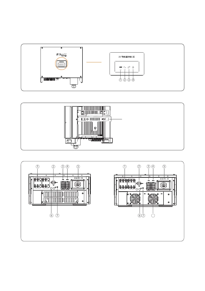
Figure 2 7 The bottom view of PV inverter.
Install the backboard
1. PV Strings connectors
2. DC Switch
3. Communications interface
4. R 485S
5. AC output connectors
6. Vent valve
7. External Protection Ground interface
8 FAN
.
2 3 2 Outline. .
Figures 2 5 to 2 7 show the outline of the inverters as follows. . :
Figure 2 5 The front view and amplification effect of LED indicator area.
1 PV Indicator.
2 Grid Indicator.
3 COM Indicator.
4 Warning Indicator.
8
10K/12K/20K
25K/30K

Table of Contents

Questions and Answers:

Question and Answer IconNeed help?

Do you have a question about the SolaX Power X3-25K-TL and is the answer not in the manual?

SolaX Power X3-25K-TL Specifications

General IconGeneral
BrandSolaX Power
ModelX3-25K-TL
CategoryInverter
LanguageEnglish

Related product manuals