21
a AC power cable Outdoor multi copper cores cables are recommended Table 5 1 describes. : - . .
the specifications.
5 2 1 Preparation. .
The AC power cable and AC terminals have been prepared with below requirements.
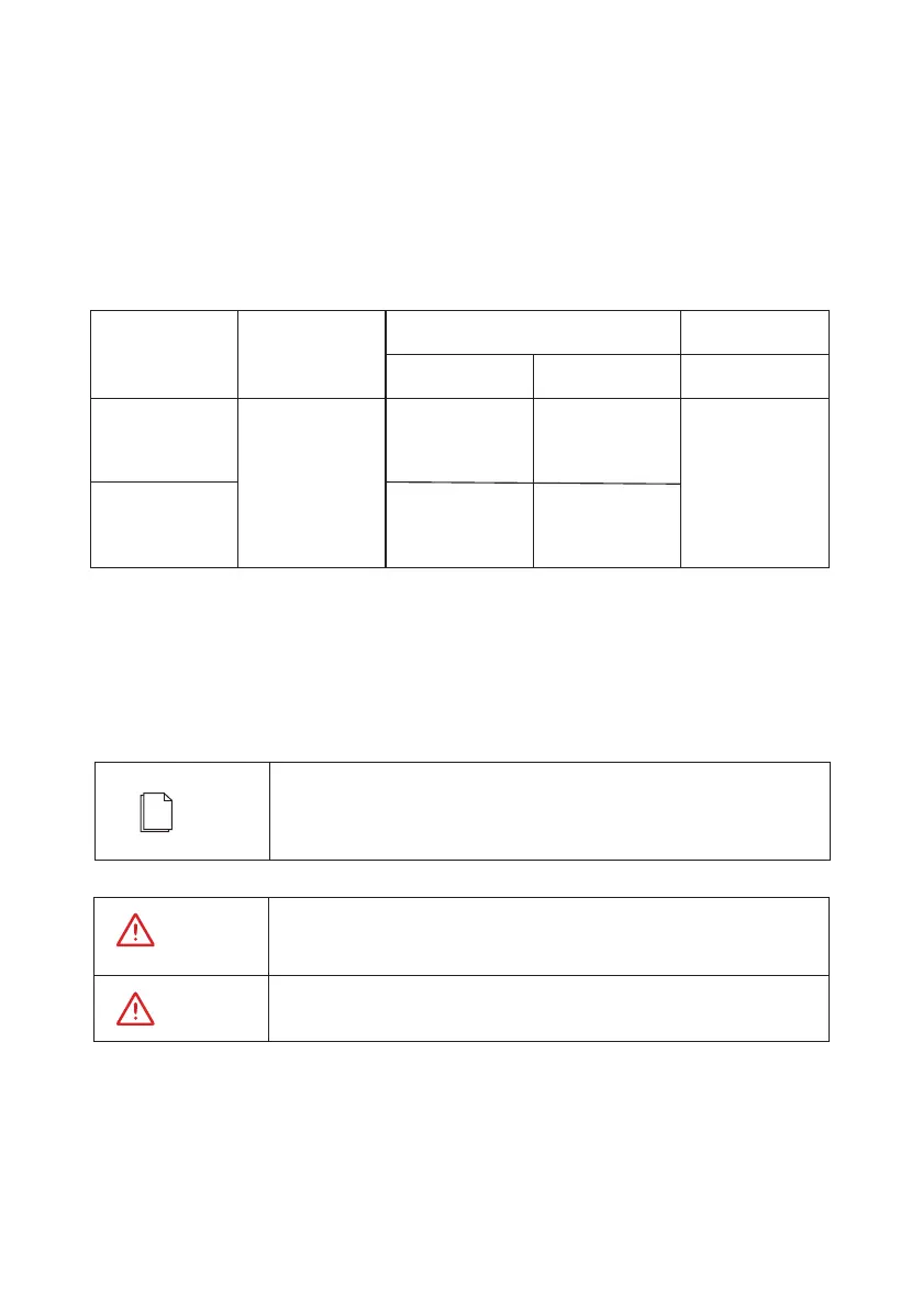
Table 5 1 Cable specifications recommended. ( )
5.2 Connecting AC Output Cables
b. OT terminals:
The inverter requires M5 OT terminals and a cable with the maximum cross-sectional area of
25 mm .
2
An independent three-phase circuit breaker must be installed on the
AC side of each inverter to ensure that the inverter can be safely
disconnected from the power grid.
NOTE
An independent three-phase circuit breaker must be installed on the AC
side of each inverter; Do not stall one circuit breaker for multiple inverters.
Do not connect loads between the AC output terminals of the inverter
and circuit breaker.
WARNING
WARNING
Inverter Model
Cable type
10K/12K/20K
6~16 10
24~32
multi-core
outdoor cable
Range
Recommended
Value
Range
Cross-sectional Area
2
Cable Outer
Diameter
( )mm
( )mm
25K/30K
10~25 16
 Loading...


