PE Connection and Leakage Current
• The end-use application shall monitor the protective conductor by residual
current operated protective device (RCD) with rated fault current Ifn≤240 mA
which automatically disconnects the device in case of a fault.
• DC differential currents are created (caused by insulation resistance and through
capacities of the PV generator). In order to prevent unwanted triggering during
operation, the rated residual current of the RCD has to be min 240 mA.
The device is intended to connect to a PV generator with a capacitance limit of
approx 700 nf.
High leakage current!
Earth connection essential before connecting supply.
• Incorrect grounding can cause physical injury, death or equipment malfunction
and increase electromagnetic.
• Make sure that grounding conductor is adequately sized as required by safety
regulations.
• Do not connect the ground terminals of the unit in series in case of a multiple
installation. This product can cause current with a d.c. component. Where a residual
current operated protective (RCD) or monitoring (RCM) device is used for protection
in case of direct or indirect contact, only an RCD or RCM of type B is allowed
on the supply side of this product.
For United Kingdom
• The installation that connects the equipment to the supply terminals shall
comply with the requirements of BS 7671.
• Electrical installation of PV system shall comply with requirements of BS 7671
and IEC 60364-7-712.
• No protection settings can be altered.
• User shall ensure that equipment is so installed, designed and operated to
maintain at all times compliance with the requirements of ESQCR22(1)(a).
For Australia and New Zealand
• Electrical installation and maintenance shall be conducted by licensed
electrician and shall comply with Australia National Wiring Rules.
0908
2.3 Explanation of Symbols
This section gives an explanation of all the symbols shown on the inverter and
on the type label.
Symbols on the Inverter
Symbol Explanation
Operating Display.
An error has occurred, please inform your installer immediately.
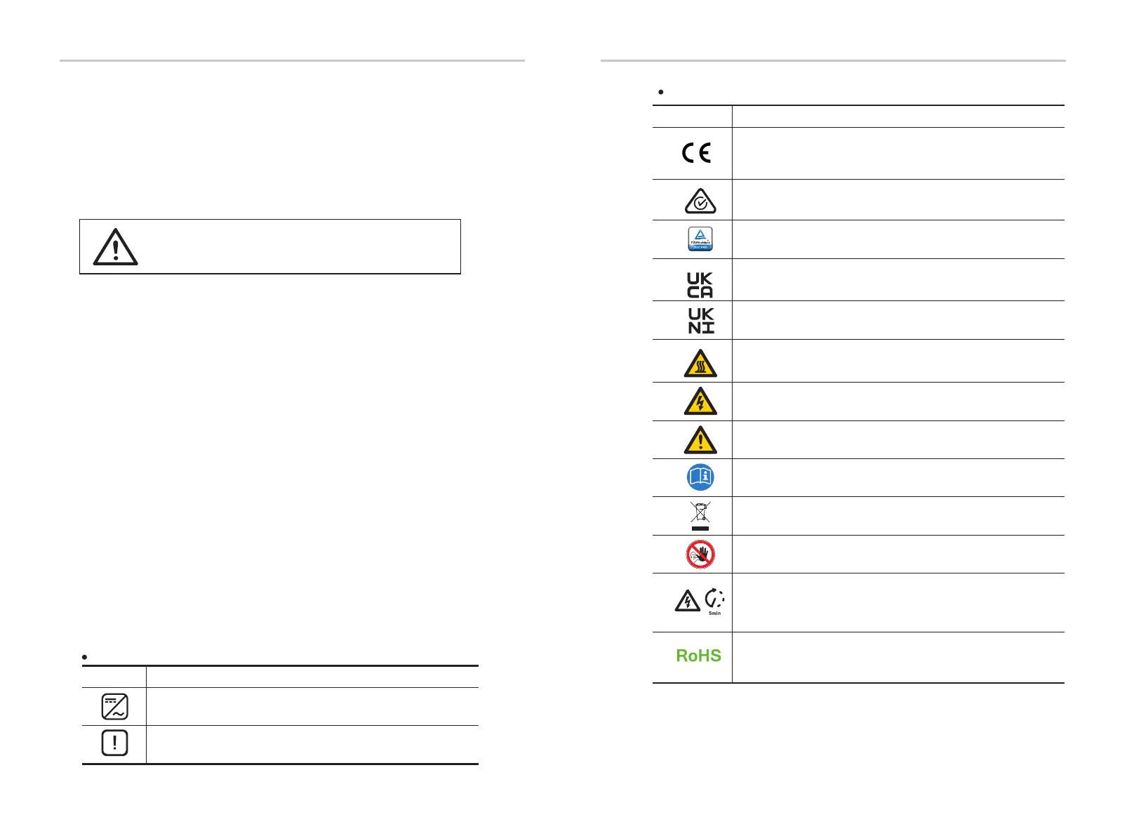
Symbols on the Type Label
Symbol Explanation
CE mark.
The inverter complies with the requirements of the applicable
CE guidelines.
RCM remark.
TUV certification.
Beware of hot surface.
The inverter can become hot during operation. Avoid contact
during operation.
Danger of high voltages.
Danger to life due to high voltages in the inverter!
Danger.
Risk of electric shock!
Observe enclosed documentation.
The inverter can not be disposed together with the household waste.
Disposal information can be found in the enclosed documentation.
Do not operate this inverter until it is isolated from mains
and on-site PV generation suppliers.
Danger to life due to high voltage.
There is residual voltage in the inverter which needs 5 min to
discharge.
• Wait 5 min before you open the upper lid or the DC lid.
Safety Safety
RoHS certificate
The inverter complies with the requirements of Restriction of
Hazardous Substances.
Compliant with UKCA standards.
Compliant with UKNI standards.
Warning!

 Loading...


