THERMOCUBE 200/300/400 THERMOELECTRIC CHILLER MANUAL 52-11300-1
SOLID STATE COOLING SYSTEMS, 167 MYERS CORNERS ROAD, WAPPINGERS FALLS, NY 12590 14
TELEPHONE: (845) 296-1300 FAX: (845) 296-1303 WEB: WWW.SSCOOLING.COM VERSION M28
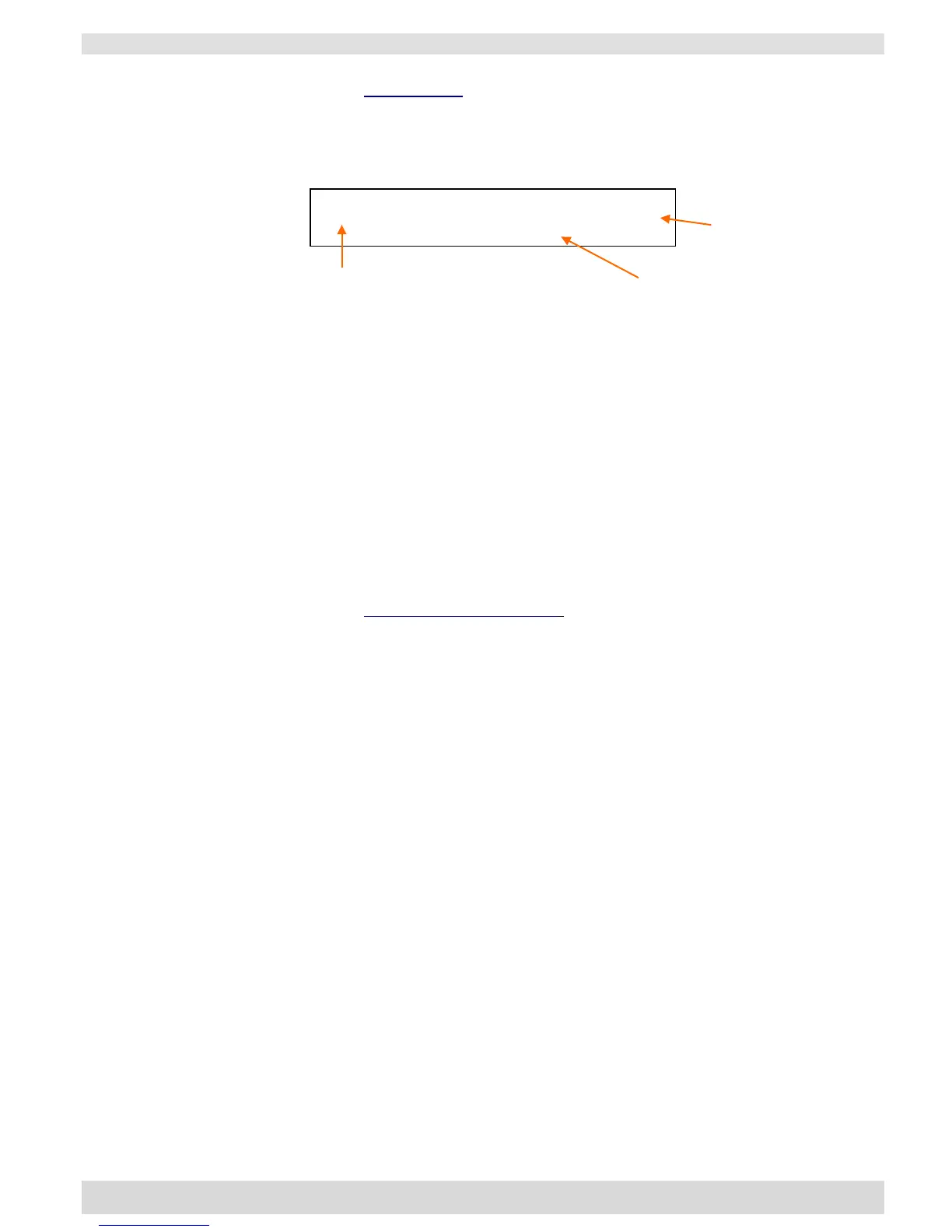
Status Menu: The status menu displays the chiller operating status
and coolant temperature. The chiller operating mode is shown in the
display’s first character: (See Figure 5)
Figure 5: Operating Display
* = Standby mode, chiller is not controlling temperature
‒ = Cooling mode, chiller is controlling temperature and process
fluid temperature is above the set point
+ = Heating mode, chiller is controlling temperature and process
fluid temperature is below the set point
The process fluid (coolant) outlet temperature is shown after TEMP
in °C or °F.
Pressing the UP or DOWN keys with the # of cycles set to zero
(default) will change the set point temperature upon pressing the
ENTER, then the START/STOP key.
Temperature Input Menu: The temperature input menu allows input
of operating temperatures, soak times, number of cycles desired, and
an optional alarm temperature. Note: If # of cycles is set to zero,
only TEMP 1 and ALARM TEMP will be used.
SETTEMP1 = Set-point of first control temperature.
If # OF CYCLES is set to zero, this is the control temperature.
SETTIME1 = Soak time at temperature 1.
Not used if # OF CYCLES is set to zero.
SETTEMP2= Set-point of second control temperature.
Not used if # OF CYCLES is set to zero.
SETTIME2 = Soak time at temperature 2.
Not used if # OF CYCLES is set to zero.
# OF CYCLES = Number of cycles between temperature 1 and
temperature 2, 0-999 cycles. If set to zero, then the
ThermoCube will continuously control at temperature 1.
ALARMTEMP = Alarm temperature range +/- set-point. The unit
will output an alarm via RS-232 when the coolant temperature
is above set-point + ALARMTEMP or below set-point
‒ ALARMTEMP.
Process Fluid Temperature