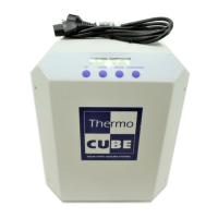
THERMOCUBE 200/300/400 THERMOELECTRIC CHILLER MANUAL 52-11300-1
SOLID STATE COOLING SYSTEMS, 167 MYERS CORNERS ROAD, WAPPINGERS FALLS, NY 12590 8
TELEPHONE: (845) 296-1300 FAX: (845) 296-1303 WEB: WWW.SSCOOLING.COM VERSION M28
3.1 ELECTRICAL CONNECTIONS (SEE FIGURE 3)
Power: The ThermoCube 200/300/400 AC power inlet is an
IEC320-C14 socket. Plug the line cord provided into this socket and
then into the appropriate 115 - 230 VAC 50/60 Hz wall outlet.
Continuous current draw is rated at 7 amps at 115 VAC or 5 amps at
230VAC (50/60 Hz). To ensure safe operation of the unit, it is
important to ensure that the outlet is properly grounded.
A wide variety of power cords are available to support universal
power operation:
NEMA 6-15 208 US Straight
India/South Africa 6A (Type D)
India/South Africa 15A (Type M)
Fuses: 10 amp (5mm x 20mm) GDB quick acting glass, meets
IEC 127-2
Replacement Fuse: SSCS#20-22332-10, Allied Electronics
#70149445.
Optional Alarms: Alarm signals are TTL signals, normally high (>4
VDC), located on the 9-pin d-subminiature connector as follows:
System Alarm: Pin 7
Alarm Signal Return: Pin 8
Temperature Alarm: Pin 9
Optional RS-232: The ThermoCube 200/300/400 has an RS-232
communication link option. Connections are made via a 9-pin dsub
connector (see section 7 for wiring and communications details).
3.2 PLUMBING CONNECTIONS (SEE FIGURE 3)
The standard process fluid inlet (coolant return) and outlet (coolant
supply) connections, located on the left side, are 1/4” John Guest
“push in” style fittings. See figure 4 for directions on using John
Guest fittings. Other fitting options are available (see section 7).
Important Note: The ThermoCube chiller should be located at
approximately the same level or above the system it is cooling to
avoid coolant draining back into the tank and overflowing after the
ThermoCube is turned off.
Hazard: Never Plug
in a Line Cord with
Wet Hands