The SolidRF MobileForce Cell Phone Signal Booster is designed to amplify cellular signals within a vehicle, improving call quality and data speeds for mobile devices. The system operates by capturing weak signals from a cell tower using an outside antenna, amplifying them through a booster unit, and then rebroadcasting the stronger signal inside the vehicle via an inside antenna. The process also works in reverse, amplifying outgoing signals back to the tower.
Function Description:
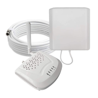
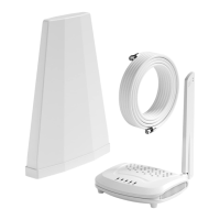
The booster system consists of four main components: an outside antenna, the booster unit, an inside antenna, and a power supply.
- Outside Antenna: This component is responsible for catching the cellular signal from the nearest cell tower. It is typically mounted on the roof of the vehicle.
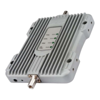
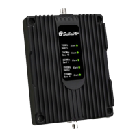
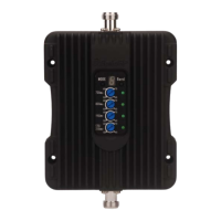
- Booster Unit: This is the core of the system, receiving the signal from the outside antenna via a coaxial cable, amplifying it, and then sending the strengthened signal to the inside antenna. The booster has indicator lights (Alarm LEDs for different bands and a Power LED) to show its operational status.
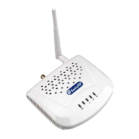
- Inside Antenna: This antenna rebroadcasts the amplified signal inside the vehicle, allowing mobile devices within its range to benefit from improved signal strength.
- Power Supply: Provides the necessary power to the booster unit.
The effectiveness of the booster is directly related to two key factors: the signal strength received by the outside antenna and the distance of separation between the outside and inside antennas. FCC regulations limit the maximum amplification to prevent damage to telecommunications infrastructure, meaning the coverage area is dependent on the original signal strength captured by the outside antenna. The system is not recommended when the outside signal strength is less than -110dBm (3G/1x) or -120dBm (4G/LTE), as the resulting boosted signal coverage would be prohibitively small.
Important Technical Specifications:
- Maximum Gain: 50dB
- Output Power: 26dBm (Uplink) / 10dBm (Downlink)
- In-band Flatness: <9dB
- EIRP: 1W Max
- Impedance: 50 ohm
- Current: ≤1.5A (12V DC)
- Supported Frequencies (MHz):
- LTE (Band 12): Uplink 698-716, Downlink 728-746
- LTE (Band 13): Uplink 776-787 (US), 777-787 (CA); Downlink 746-757 (US), 746-756 (CA)
- Cellular (Band 5): Uplink 824-849, Downlink 869-894
- PCS (Band 25/2): Uplink 1850-1915, Downlink 1930-1995
- AWS (Band 4): Uplink 1710-1755, Downlink 2110-2155
Usage Features:
- Signal Strength Measurement: Users are advised to measure signal strength in decibels (dBm) and identify the band number on their phone before installation. For iPhones, this can be done by dialing 3001#12345# and pressing call. For Android, a third-party app like "LTE Discovery" is recommended. This helps in understanding the baseline signal and evaluating the booster's performance.
- Installation Planning: Step-by-step instructions guide users through studying their vehicle for optimal antenna placement. A minimum separation distance of 3 feet horizontally and 2 feet vertically is required between the inside and outside antennas to prevent self-oscillation.
- Antenna Placement:
- Outside Antenna: Should be placed on the rear of the roof to maximize distance from the inside antenna. It has a powerful magnet for attachment to ferrous surfaces; an iron sticker is provided for non-ferrous roofs. Cables can be routed through the back door or trunk.
- Inside Antenna: Should be placed at the lower side of the driver's seat, or where the cell phone is used most often, ensuring it is parallel to the horizontal plane. It uses two powerful Velcro strips for attachment.
- System Connection: Simple connection process: outside antenna cable to the "OUTSIDE" port on the booster, inside antenna cable to the "INSIDE" port, and then plug in the power adapter.
- Performance Evaluation: After installation, users should run a signal strength/speed check with the booster off and then on to observe improvement. The booster performs a self-diagnostic upon power-on, indicated by the LED light flashing for 1 second and then turning off if everything is connected correctly.
- Coverage Area: The coverage area around the inside antenna varies with the outside signal strength:
- Strong (5 bars): 8 ft radius
- Medium (3-4 bars): 4 ft radius
- Weak (1-2 bars): 2 ft radius
Maintenance Features:
- Troubleshooting: The manual provides guidance for common issues:
- No Signal Improvement: Check if the indoor unit is plugged in and the Power Light is green. Verify that the incoming signal level at the outdoor antenna position is sufficient (not less than -110dBm for 3G/1x or -120dBm for 4G/LTE).
- Self-Oscillation: If any front panel lights are flashing green then off, or continuously flashing/solid green, it indicates self-oscillation. Users must switch off the booster and immediately check the separation between the outside and inside antennas to ensure minimum separation requirements are met.
- Warranty: The booster is covered by a three-year product warranty for failures or defects resulting from craftsmanship and/or materials. Proof of purchase is required for warranty claims. Users can contact the retailer/reseller or SolidRF directly. The warranty does not cover misuse, abuse, neglect, tampering, or mishandling.
- Safety Guidelines:
- Maintain a minimum separation distance of at least six feet between the inside and outside antennas.
- Maintain at least four feet of separation distance from the inside unit.
- Use only the provided power supply.
- The inside unit is designed for indoor, temperature-controlled environments (below 100 degrees Fahrenheit).
- Any antenna used with the device must be located at least 8 inches from all persons.
- FCC/ISED Compliance: The device complies with FCC rules and ISED CPC-2-1-05 requirements. Users must register the device with their wireless provider and obtain consent. Antennas must be installed at least 20 cm (8 inches) from any person. Operation must cease if requested by the FCC or ISED.
- Customer Support: Contact information for customer service (Office: (435) 319-6858, Toll Free: (877) 579-7878) and email support (US: Support@SolidRFINC.com, Canada: Support@SolidRF.ca) is provided for questions or concerns.