EasyManua.ls Logo

SolidRF Signal Plus - User Manual

SolidRF Signal Plus
20 pages
Print Icon
To Next Page IconTo Next Page
Loading...
Signal Plus
Cell Phone Signal Booster
Manual
1
Manufactured and Warranted by
SolidRF Inc.
www.solidRFinc.com
customer service number:
Office (435) 319-6858
Toll Free (877) 579-7878
Operational Diagram
(How It Works)
Package Contents
Page 2
Installation Step By Step
Page 8 - 16
Trouble Shooting
Page 17 - 18
Technical Specification
Warranty Information
Page 19
Basic Signal Level Knowledge
Page 3
Preparation
Page 4 - 7
Safety Guidelines
Page 20
Question and Answer IconNeed help?

Do you have a question about the SolidRF Signal Plus and is the answer not in the manual?

Summary

Operational Diagram and Package Contents

Working Diagram Explained

Explains the signal booster's operational flow and how it works.

Package Contents Overview

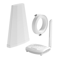
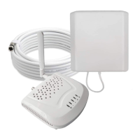
Lists all items included in the signal booster kit for installation.

Signal Level Knowledge

Signal Transmission Loss and Power Levels

Illustrates signal strength categories and power levels based on distance from the cell tower.

Coverage Area Ability Explained

Details how signal strength at the antenna location affects coverage area.

Preparation Steps

Locate Your Cell Tower

Guides users to use Cellmapper.net to find the nearest cell tower for optimal setup.

Map Navigation and Area Zoom

Instructs users to locate their specific area on the map for detailed analysis.

Select Network Provider

Guides users to select their specific mobile carrier on the mapping tool.

Identify Base Station Details

Explains how to interpret base station information like coverage area and frequency bands.

Measure Signal Strength (dBm)

iPhone dBm Measurement

Provides instructions for iPhones to access field test mode for signal strength.

Android dBm Measurement

Guides Android users to use the LTE Discovery app for signal strength readings.

Installation Steps

Outside Unit Location Selection

Details how to choose the best location for the outdoor antenna to capture the strongest signal.

Optimal Outdoor Antenna Placement

Recommends specific positions like corners facing the cell tower for the outdoor antenna.

Temporary Outside Antenna Mounting

Explains mounting options for the outdoor antenna, including height restrictions and lightning safety.

Outdoor Antenna Mounting Cautions

Warns about tree interference and FCC height regulations for outdoor antennas.

Inside Antenna Location Selection

Provides guidelines for placing the indoor antenna, including separation distances.

Measure Indoor Signal Strength

Instructs users to test and record signal strength at various indoor locations.

Antenna Beam Characteristics

Describes the radiation patterns of both indoor and outdoor antennas.

Antenna Mutual Positioning Guidelines

Illustrates correct and incorrect positioning of indoor and outdoor antennas to avoid interference.

System Connection Steps

Details the initial connection steps for the signal booster system.

Connecting System Components

Guides users through connecting the outdoor antenna, indoor antennas, splitter, and power adapter to the booster.

Evaluate Booster Performance

Instructs users to re-test signal strength and compare it to initial readings to confirm booster functionality.

Decibel Gain vs. Performance Metrics

Presents a table showing the relationship between decibel gain and power/distance/coverage enhancement.

Finalizing Outdoor Antenna Installation

Provides final steps for securing the outdoor antenna, including mounting options and cable management.

Sealing and Securing Outdoor Connectors

Advises on properly sealing and securing outdoor antenna connectors against weather and wind damage.

Finalizing Indoor Installation

Covers the final placement, mounting, and connection of the indoor antenna and booster unit.

Securing Cable Routes

Details how to route and secure cables to ensure system reliability and prevent damage.

Handling Excess Cables

Provides guidelines on managing coiled cables to prevent system instability and ensure proper operation.

Troubleshooting Guide

Booster Correct Functioning Indicators

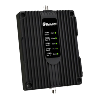
Explains the meaning of the power light and panel state lights for correct operation.

Troubleshooting No Signal Improvement

Provides steps to diagnose and resolve issues when the signal booster is not improving signal.

Troubleshooting Tree Interference

Advises on adjusting the outdoor antenna height relative to trees when signal is weak.

Troubleshooting Oscillation Issues

Guides users to identify and resolve self-oscillation by checking antenna separation and direction.

Minimum Separation Distance Requirements

Restates the critical separation distances required between indoor and outdoor antennas.

Technical Specifications and Warranty

Technical Specifications

Details the technical parameters and performance metrics of the signal booster.

Product Warranty Information

Outlines the terms and conditions of the three-year product warranty.

Safety Guidelines and Compliance

General Safety and RF Warnings

Covers essential safety precautions for using the signal booster and antenna placement.

Consumer Device Registration and Compliance

Explains the requirements for registering the device with wireless providers and FCC compliance.

Overview

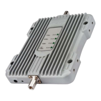
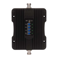
This document describes the SolidRF Signal Plus Cell Phone Signal Booster, a device designed to amplify cellular signals for improved coverage indoors.

Function Description:

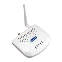
The SolidRF Signal Plus Cell Phone Signal Booster system works by capturing existing cellular signals from a nearby cell tower, amplifying them, and then rebroadcasting the boosted signal indoors to mobile devices. The process also works in reverse, amplifying outgoing signals from mobile devices back to the cell tower. The system consists of an outdoor antenna, a booster unit, indoor antennas, a power supply, a splitter, and RG6 cables.

The outdoor antenna is responsible for catching the signal from the cell tower. This signal is then sent to the booster through a coax cable. The booster amplifies the signal and distributes it to the indoor antennas, which rebroadcast it throughout the coverage area. The effectiveness of the booster, including the size of the coverage area and the strength of the boosted signal, is directly related to two key factors: the signal strength received by the outdoor antenna and the distance of separation between the outdoor and indoor antennas. Optimal performance is achieved when the external antenna is placed where the signal is strongest and there is sufficient separation between the indoor and outdoor units.

The manual emphasizes the importance of a test installation to ensure optimal performance. This involves selecting the best location for the outdoor unit, typically on the side of the house facing the nearest cell tower where the signal is strongest. The ideal installation position is often a corner of the building. The height of the outdoor antenna should not exceed the highest point of the house to prevent damage from lightning strikes. It also cautions against placing the outdoor antenna too close to tall trees, as trees can significantly attenuate wireless signals. For indoor antenna placement, it is crucial to ensure a minimum separation distance from the outdoor unit (over 30 feet straight line, or 20 ft horizontal and 13 ft vertical distance) and to avoid facing the outdoor antenna directly. The indoor antenna is a panel directional antenna, and its placement should maximize coverage within the home.

The system supports multiple frequency bands, including LTE (bands 12, 13), Cellular (band 5), PCS (bands 25/2), and AWS (band 4), indicating its compatibility with various cellular networks and technologies.

Important Technical Specifications:

  • Frequency (MHz):
    • Uplink: 698-716 (band 12), 776-787 (band 13), 824-849 (band 5), 1850-1915 (band 25/2), 1710-1755 (band 4)
    • Downlink: 728-746 (band 12), 746-757 (band 13), 869-894 (band 5), 1930-1995 (band 25/2), 2110-2155 (band 4)
  • Gain:
    • Uplink: 62 dB (bands 12, 13, 5), 65 dB (bands 25/2, 4)
    • Downlink: 65 dB (bands 12, 13, 5), 68 dB (bands 25/2, 4)
  • Output Power: 23dBm (Uplink) / 6dBm (Downlink)
  • Noise Figure: <5dB
  • In-band Flatness: <9dB
  • Weight: 0.65Kg
  • EIRP: 1W
  • Impedance: 50 ohm
  • Operating Temperature: 5°F to 140°F (-15℃~60℃)
  • Current: ≤1.5A (12V DC)
  • Dimensions (mm/in): 15812525 / 6.24.870.98
  • Coverage Area Ability: The maximum coverage area depends on the original signal strength captured by the outdoor unit. For strong outdoor signals (5 bars on cellphone), coverage can reach 5,000 sq. ft. with one antenna or 8,000 sq. ft. with two antennas. For weak signals (1-2 bars), coverage is significantly reduced to 600 sq. ft. (one antenna) or 1,000 sq. ft. (two antennas).
  • Minimum Required Separation Distance between Indoor and Outdoor Antennas: Over 30 feet (10 meters) straight line distance, or 20 ft (6 meters) horizontal distance and 13 ft (4 meters) vertical distance.

Usage Features:

  • Signal Level Knowledge: The manual provides a clear guide to understanding signal strength in dBm for both 3G/1X and 4G/LTE, indicating what constitutes excellent, good, fair, poor, and dead zone signals. It also includes instructions on how to find dBm readings on both iPhone and Android devices.
  • Cell Tower Location: Users are guided to use www.cellmapper.net to locate nearby cell towers and identify the best direction for outdoor antenna placement, which is crucial for optimal performance.
  • Installation Flexibility: Offers options for mounting the outdoor antenna on a roof pole or the side of a chimney.
  • Multiple Indoor Antennas: The kit includes two indoor antennas and a splitter, allowing for broader indoor coverage.
  • Indicator Lights: The booster features LED lights on the front panel that indicate its status. A solid white logo indicates power, and green indicator lights (which turn on briefly during self-check and then go out) signify good condition. Flashing green lights or intermittent lights indicate self-oscillation, requiring adjustment of antenna separation.
  • Safety Guidelines: Emphasizes maintaining separation distances between antennas, using the provided power supply, and ensuring the indoor unit is in a temperature-controlled environment. It also includes FCC and ISED (Canada) compliance information, requiring device registration with wireless providers.
  • Customer Support: Provides contact information for customer service via office phone and toll-free number, as well as email addresses for US and Canada support.

Maintenance Features:

  • Cable Management: Instructions are provided for securely connecting and routing cables to prevent damage from wind or gravity, especially for the outdoor antenna. It recommends forming a single turn shape with the cable near the antenna and sealing connectors with glued tape to protect against rain and moisture erosion.
  • Excess Cable Handling: Advises keeping excess coiled cables more than 6 feet (2 meters) away from antennas or the booster to maintain system stability.
  • Troubleshooting Guide: A dedicated section helps users diagnose common issues such as no signal improvement. This includes checking power, cable connections, incoming signal level at the outdoor unit, and outdoor antenna direction. It also addresses self-oscillation indicated by flashing lights, guiding users to adjust antenna separation.
  • Ventilation: Recommends mounting the booster in a ventilated and dry place, away from heat, and not covering it, as the booster can operate at temperatures about 30 degrees Fahrenheit higher than ambient.
  • Warranty: The product comes with a three-year warranty covering failures or defects from craftsmanship and materials. Users are advised to retain proof of purchase and contact the retailer/reseller or SolidRF directly for warranty claims. The warranty does not cover misuse, abuse, neglect, tampering, or mishandling.

SolidRF Signal Plus Specifications

General IconGeneral
BrandSolidRF
ModelSignal Plus
CategoryExtender
LanguageEnglish

Related product manuals