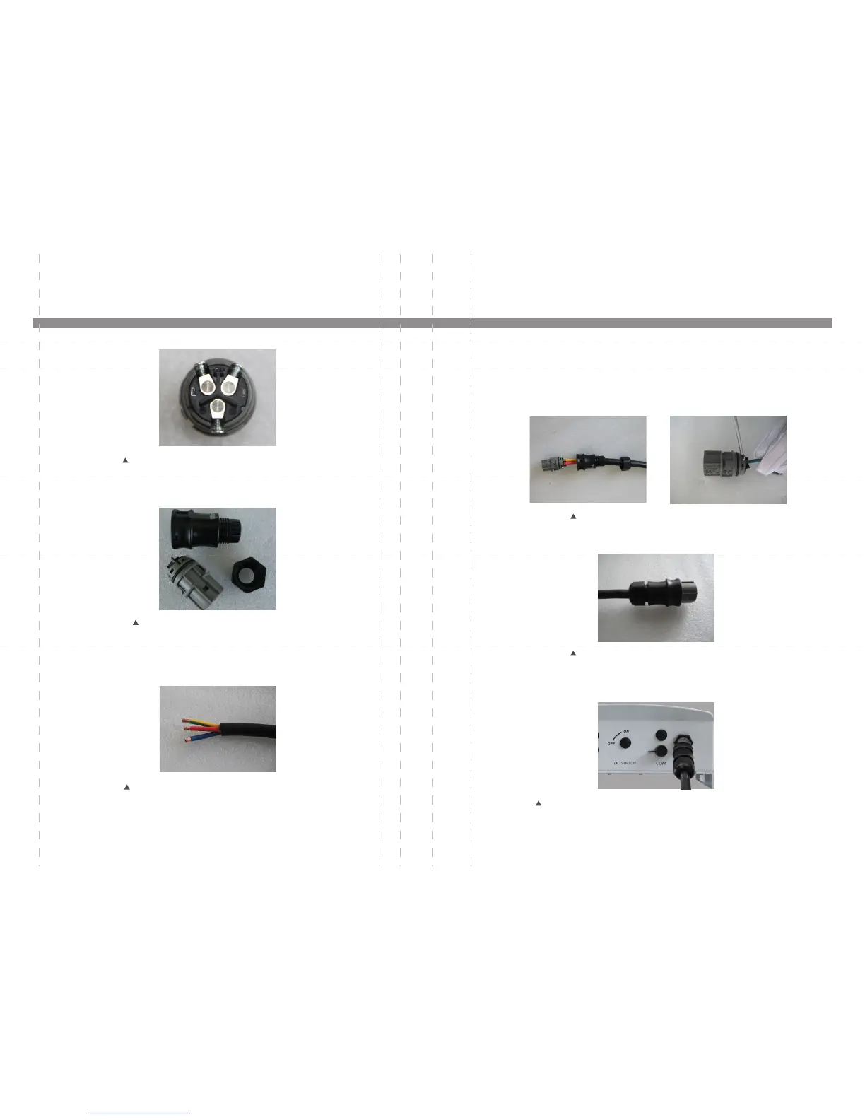
Figure 4.12 AC Grid Terminal Connector
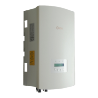
Figure 4.11 AC Grid Terminal Connector Inside
The steps to assemble the AC grid terminal connectors are listed as follows:
a) Disassemble the AC connector. Strip the AC wires about 6mm,
c) Tighten the cap nut to the terminal (as shown in Figure 4.15).
Figure 4.13 Stripped AC Wires
Figure 4.15 Tight Up the Cap on the Terminal
d) Connect the AC grid terminal connector to the inverter. Small click will confirm
connection (as shown in Figure 4.16).
Figure 4.16 Connect the Terminal Connector to the Inverter
4. Installation 4. Installation
Each Solis Single Phase Inverter is supplied with an AC grid terminal connector, which is
shown in Figure 4.12.
.15. .16.
b) Fix the green and yellow wire to the ground terminal. Fix the red(or brown) wire to L
(line) terminal. Fix the blue wire to N(Neutral). Tight the screws on the connector (as
shown in Figure 4.14). Please try to pull out the wire to make sure the it’s well
connected.
Figure 4.14 Connect Wires to the Terminal