S
sullivandouglasSep 18, 2025
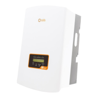
What does PV ISO-PRO 01/02 mean on my SOLIS Inverter?
- VvmooreSep 18, 2025
The PV ISO-PRO 01/02 error on your SOLIS Inverter indicates that the inverter detects low DC insulation resistance. Inspect the installation, reset the inverter, and note the weather conditions when the alarm occurs. Measure the insulation resistance; if it's normal, measure it again in the same weather conditions as when the alarm occurred. Physically check the cables. If the problem persists, replace the inverter.