User Manual
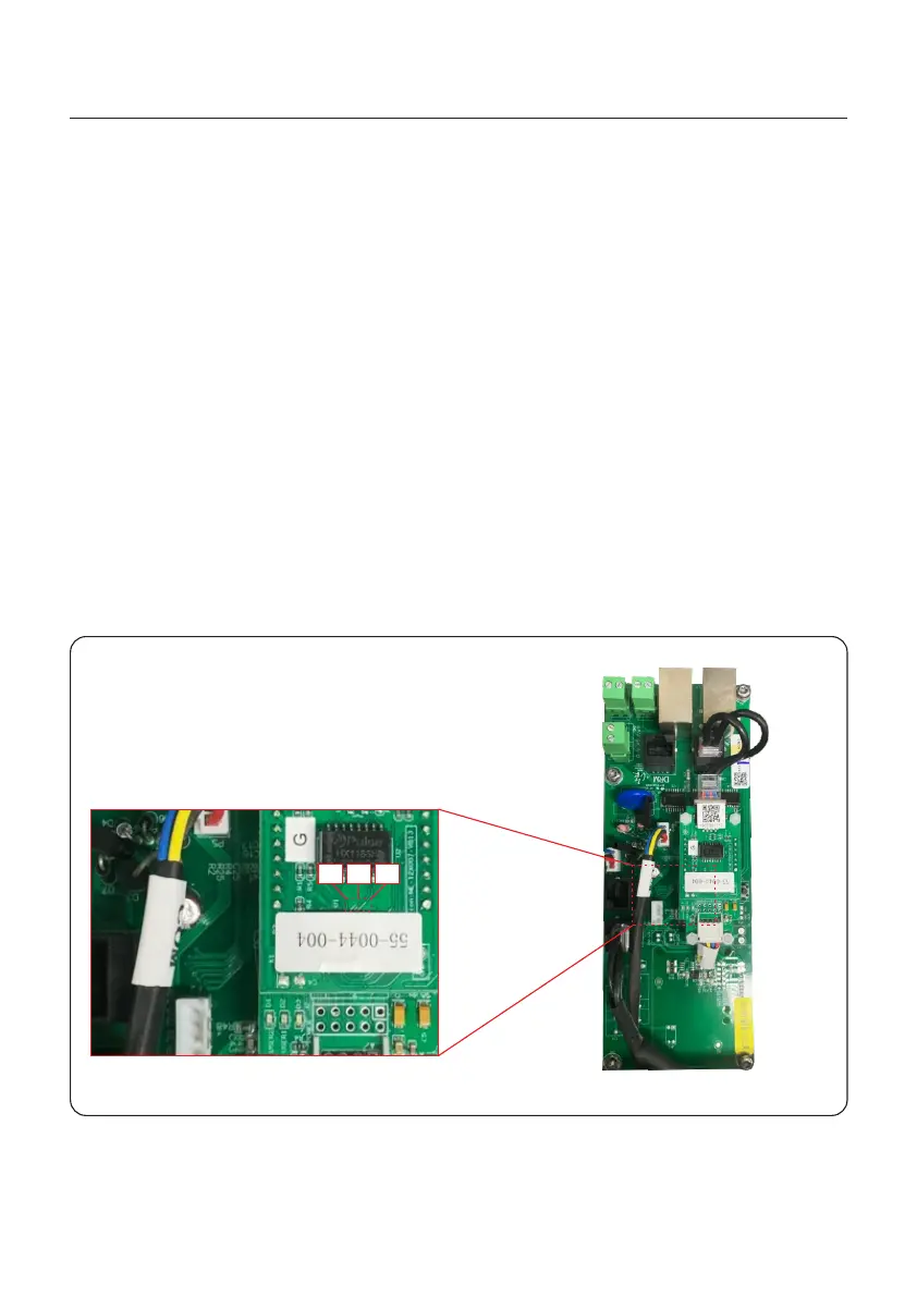
5. Ethernet Module LED Indicators
D1 Red LED: Indicator between module and inverter.
Constantly ON indicates normal connection.
Blinking indicates it is trying to connect.
OFF indicates connection failed.
Constantly ON but blinking sometimes indicates it is transferring data between inverter.
D1 and D2 slowly blinking alternately or slowly blinking synchronously indicates abnormal
network issue.
D1 and D2 both OFF with D3 ON indicates the module is initializing.
D2 Red LED: Indicator between module and server.
Constantly ON indicates normal connection.
Blinking indicates it is trying to connect.
OFF indicates connection failed.
Constantly ON but blinking sometimes indicates it is transferring data between the server.
D3 Green LED: Module power light.
Constantly ON indicates power supply normal.
OFF indicates power supply abnormal.
Figure 4.13
D3D2D1
4. Comm. & Monitoring
35