User Manual
This function is for maintenance personnel only, wrong operation
will prevent the inverter from reaching maximum power.
2. Volt-Watt (Not Required)
Description: Inverter will change the active output power based on voltage change.
Note: This Setting is NOT required by UL1741SA Standards.
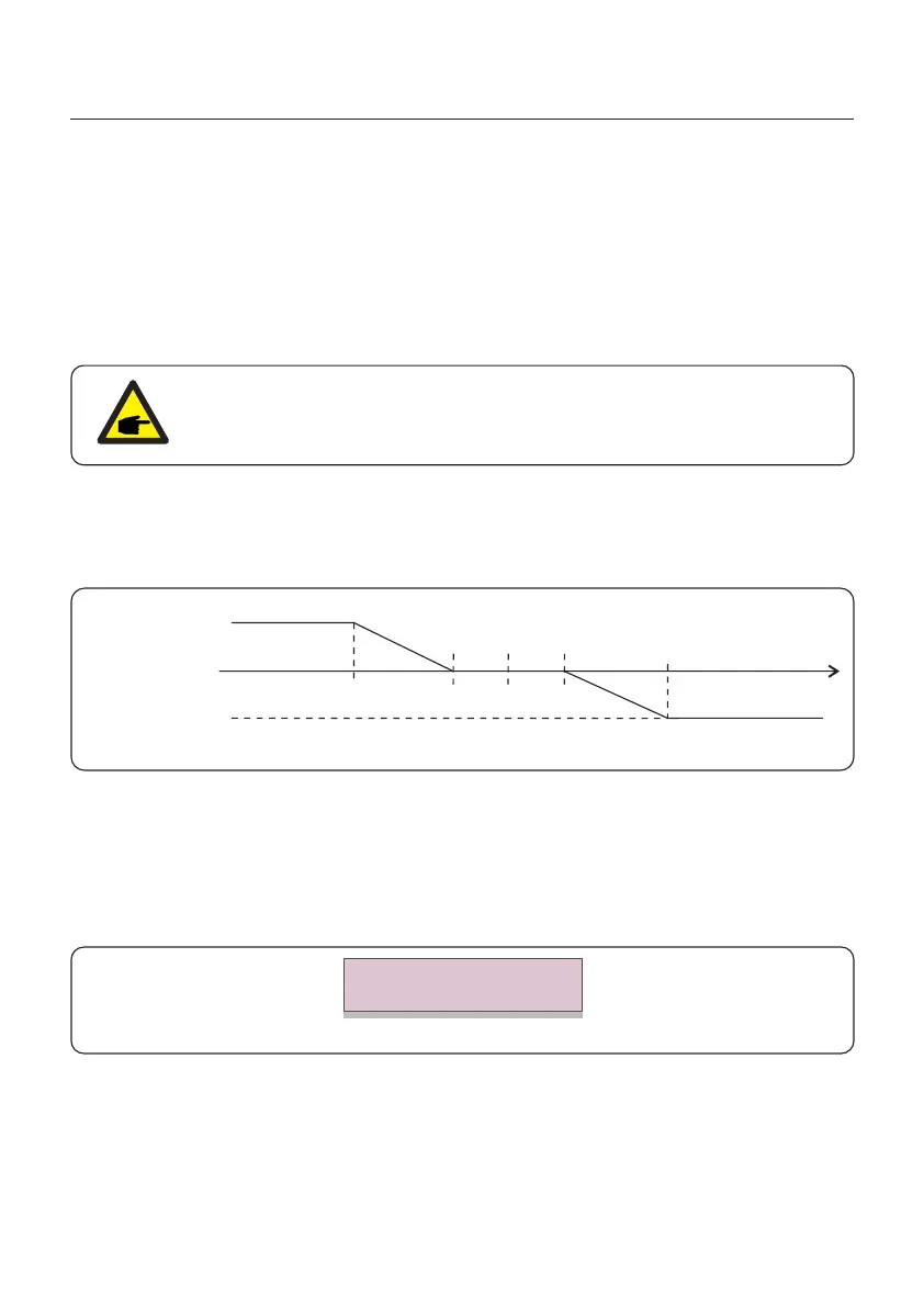
3. Volt-Var (Default)
Description: Inverter will change the reactive output power based on voltage change.
Q1,cap
Q2=Q3=0
Q4,ind
V1 V2 Vnom V3 V4
Figure 6.21 Volt-VAR curve for Q(V)
Default Settings for UL1741SA:
Q1: (0-60%) Default +30% Q4: (-60%-0%) Default -30%
Rated 480V Grid
V1:(221-279V) Default 242V V2: (221-279V) Default 273V
V3:(277-320V) Default 281V V4: (277-320V) Default 305V
Figure 6.22 Volt-VAR
Voltage1: 242V
Voltage2: 273V
1.NULL
Description: Inverter is not under any working mode.
6. Normal operation
52
NOTE
 Loading...