Preparing the equipment for use
ENGLISH 9
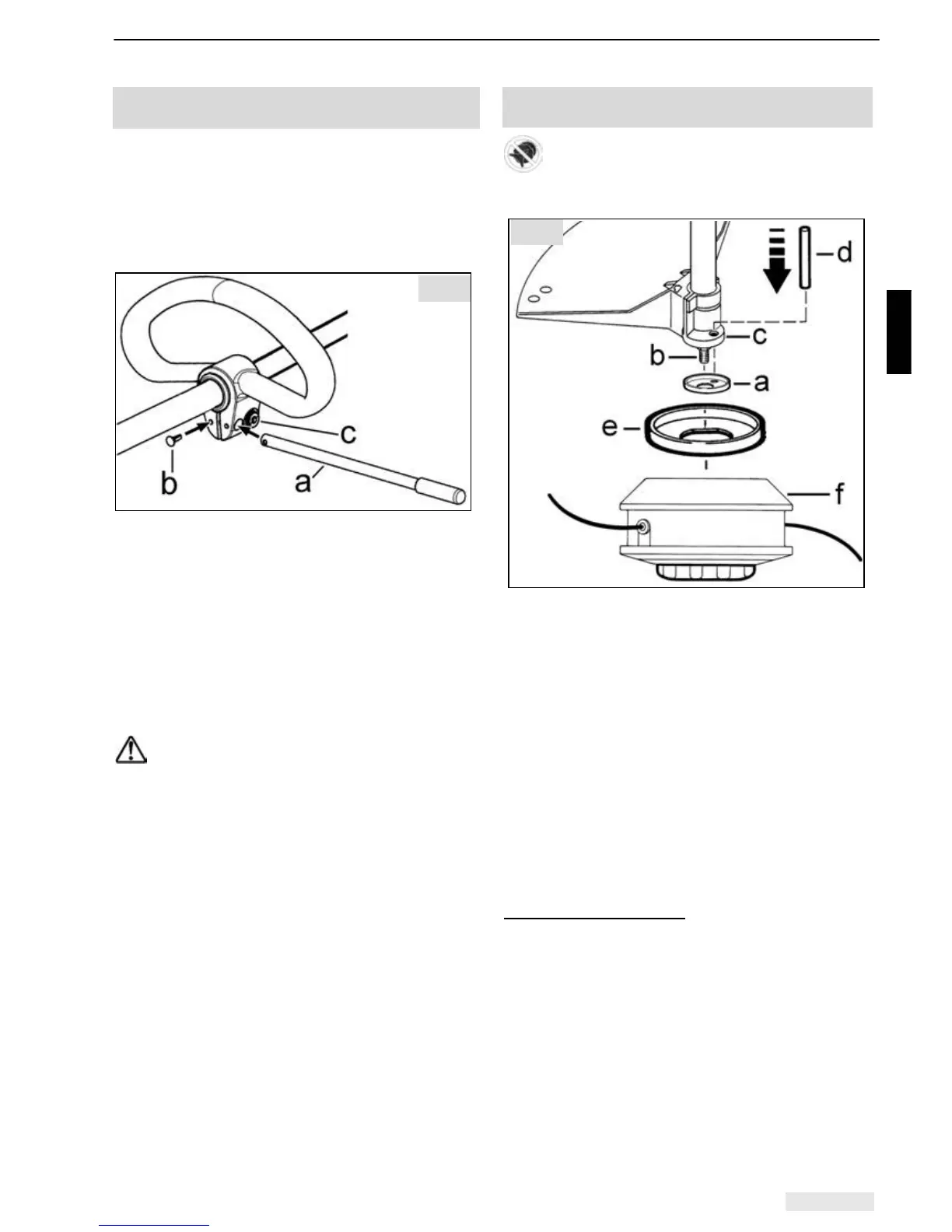
5.2 Fitting the safety end-stop on the loop
handle - model 104L
Always install the safety end-stop (a) on the
operator side of the power tool.
If, during use, you carry the power tool on your r.h.
side, install the safety end-stop in l.h. orientation.
However, if, during use, you carry the power tool
on your l.h. side, install the safety end-stop in r.h.
orientation.
Install the safety end-stop (a) on the loop handle
and secure with the spring clip (b).
The position of the loop handle can be moved
along the shaft tube after loosening screw (c)
(Torx-25), and thus be positioned to suit the height
of the user.
Finally, tighten screw (c), holding the nut opposite
it in place with an open-ended spanner to stop it
turning as well.
In general, before starting work, check the
loop handle and safety end-stop are
seated tightly and correctly.
Model 104L
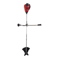
5.3 Fitting and replacing the line head -
model 104L
Always switch off the engine, pull the spark
plug cap and wear protective gloves when fitting or
replacing the cutter!
• Carefully place cup washer (a) on drive shaft
(b). Ensure that the edge of the cup washer is
pointing upwards and covers the rim of flange
casing (c).
• Turn the drive shaft with the cup washer until
the hole in the cup washer and the hole in the
flange casing are precisely one above the other.
• Use locking pin (d) to lock the drive shaft.
• Place anti-winding protection (e) (included in
standard delivery of line head) on the cup
washer so the rim of the anti-winding protection
covers the rim of the cup washer.
• Secure line head (f) to drive shaft (clockwise –
standard right-handed thread).
Removing the line head
• Turn the line head until the hole in the cup
washer and the hole in the flange casing are
precisely one above the other and the locking
pin can be inserted.
• Unscrew the line head in an anti-clockwise
direction.
Fig. 3
Fig. 4