Preparing the equipment for use
ENGLISH 11
Model 107L / 107B
5.7 Assembling and replacing the cutting tool - model 107L/ B
Always switch off the engine, pull the spark plug cap and wear protective gloves when fitting or replacing
the cutter!
Subject to model version, a line head or metal cutting blade (4-tooth grass cutting blade / 3-tooth brush
cutting blade) is included as the cutting tool in the standard delivery of your power tool.
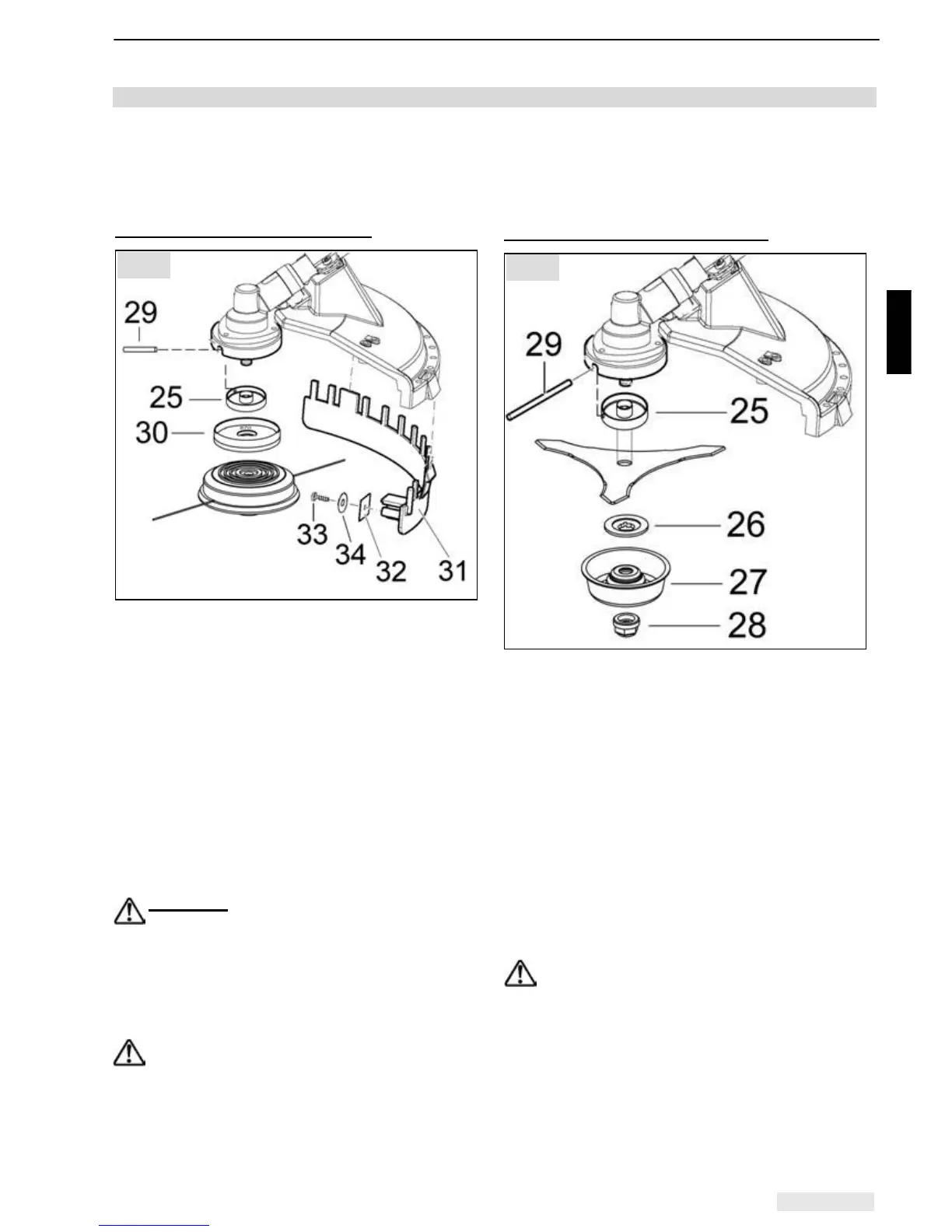
A) Assembly of the nylon line head
• Fit the anti-winding protection (30) (supplied
with the line head) after the pressure piece (25).
The side of the anti-winding protection labelled
with the number "871" faces the gearbox, so
the edge of the anti-winding protection overlaps
the edge of the bevel gearbox.
• Block the shaft with the pin (29).
• Screw on the line head by hand. Caution: left-
handed thread.
• •Fit the line cutter blade (32) with screw (33)
and washer (34) to the protective bar (31).
• Fit the protective bar (18) with assembled line
trimmer from underneath onto the guard. Bend
the protective bar slightly in the process.
Important:
When using the line head, never
start the power tool without the protective bar
and the line trimmer assembled.
If the length of the line has been adjusted (see
chapter 8.4, "Adjusting the cutting line"), the line
trimmer will automatically cut the ends of the line
to the correct length during operation.
When using metal cutting blades, always
work without the protective bar fitted.
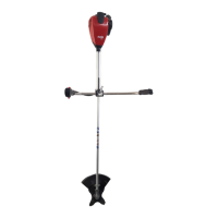
B) Assembling metal cutting blade
• Position the power tool with the output shaft
facing upwards.
• Place the brush cutting blade on the pressure
piece (25). In order to centre the cutting blade,
the shoulder of the pressure piece must be
located exactly in the bore of the cutting blade.
• Fix the pressure washer (26).
• Place the nut protector (27) and turn safety nut
(28) onto the shaft.
Caution! Left hand thread - tighten counter
clockwise.
Take care that all parts are centered.
• Block the shaft with the stop pin (4) and tighten
nut.
It is imperative that the safety nut (28) is
replaced, if it has become loose due to
frequent rem oval and tightening.
Afterwards check that the cutting blade is securely
seated and that it is properly centred.
Fig. 8
Fig. 9