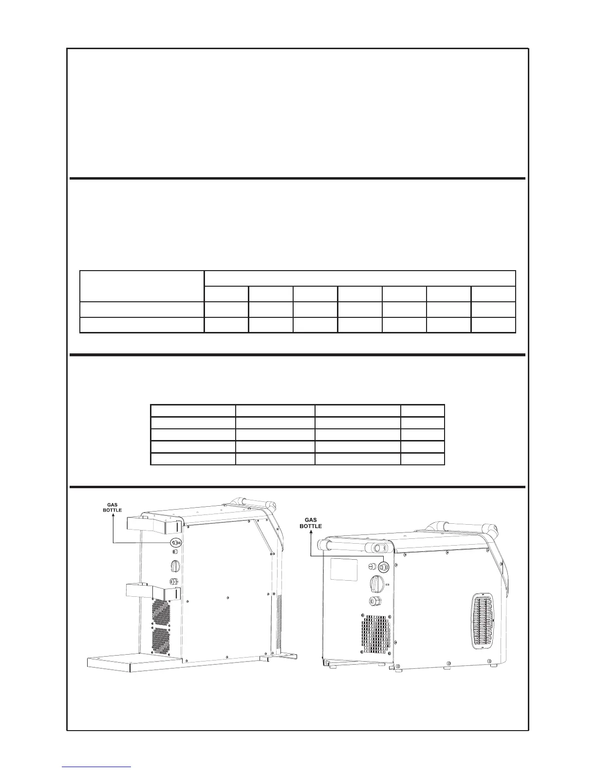
1 - Control panel
2 - Negative pole connector
3 - Euroconnector
4
- Gas connector
5 - Aerofeed connector
6 - Positive pole connector
7 - Gas input
8
- 2A Fuse (control)
9 - Main switch
10 - Mains connection
CONNECTION OF THE EARTH CLAMP
T
he earth clamp must be connected as close as possible to the workpiece and the other side of the cable must be
c
onnected to the machine (in the desired position according with the polarity). The contact surface with the workpiece
should be as large as possible. Make sure that the surface is completely clean and free of paint and rust.
The following table shows the cable section, recommended by Solter Soldadura, according to amperage and opera-
ting cycle for lengths of less than 25m. These data are for reference and may NOT suit all applications. If the cable
overheats, use a larger cable section.
CONNECTION OF THE TORCH
Connect the MIG torch in its position taking special care to ensure it is tightly screwed. Make sure that the torch is
going to be used is suitable for the current levels and operating cycle that the application requires. You can use an
air-cooled or water-cooled torch. Solter has different torches to suit the needs of each customer. See table below.
GAS CONNECTION
Welding current (A)
100 150 200 250 300 350 400
Section (mm
2
) for X<60% 16 25 25 35 50 50 70
Section (mm
2
) for X>60% 16 25 35 50 70 70 90
TORCH REFRIGERATIÓN DUTY CICLE REF.
SX-36 4m Air 270A 60% 56033
SX-36 3m ALU Air 270A 60% 56077
SX-501 4m Liquid 500A 60% 56075
SX-501 3m ALU Liquid 500A 60% 56078
SOLTER SOLDADURA S.L.
AEROPROCESS
6