18
© 2011 Somfy SAS. All rights reserved. 09/2011
EN
Danger!
Live electric cables
Î Danger of electric shock if touched!
Disconnect all connected cables from the power supply before
working on the installation!
Take preventive measures to avoid any unwanted operation!
7KLV6RPI\SURGXFWPXVWEHLQVWDOOHGE\DWHFKQLFDOO\TXDOLILHGSHUVRQ
for whom this guide is intended. The professionally qualified person must
comply with all the standards and legal provisions in force in the country of use.
The J4 power supply cable must never be powered while disconnected from the motor.
A J4 motor must never be supplied without its dedicated cable.
This motor must not be connected to an isolating transformer.
When you use a switch, a maximum of 3 motors, with a total cable length of 50 m, can be
connected in parallel.
The phases and neutrals must be connected together respectively.
Do not use more than one switch connected to each motor.
In case of drive by a controller or any automatisms, please refer to the dedicated instructions
manual.
The movement is correctly executed by the motor, only if it received a continuous order for at
least 200 ms.
For commands sent to the motor to be executed correctly, they must be at least 500 ms apart.
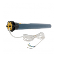
4. Electrical connection
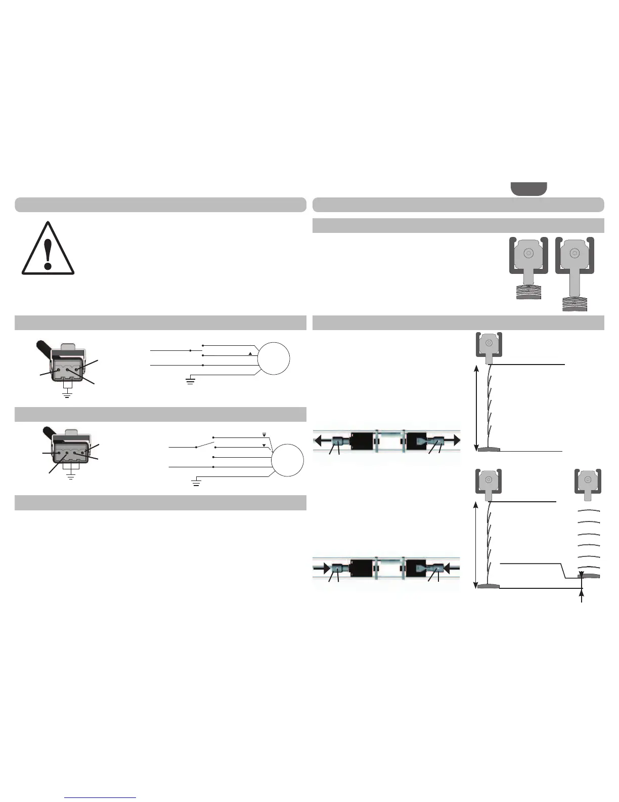
4.1. 1TN / HTM / WT
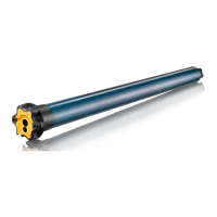
4.2. 2TN
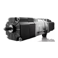
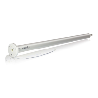
6SpFL¿FLWpV-:7
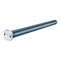
The mushroom is used for the upper end limit position.
To adjust the height of the mushroom, use the extensions
described in section 2.3.
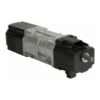
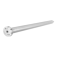
5. 1TN/2TN: Setting the end limits
5.1. Upper end limit position
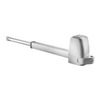
5.2.
Lower end limit (1TN)/lower end limit no. 2 (2TN) position
The lower end limit position cannot be adjusted on
the motor. The motor is supplied ex. factory in the
lower end limit position.
To change the lower end limit position on
the exterior Venetian blind, use the following
procedure:
If necessary, loosen the grub screws (7), then
disconnect the drive shafts from the motor shaft
adaptors (1).
Rotate the motor downwards until it stops in the
lower end limit position.
Position the exterior Venetian blind in the
required lower end limit (1TN)/lower end limit
no. 2 (2TN) position.
Connect the drive shafts to the motor shaft
adaptors (1), then, if necessary, fully tighten the
screws (7).
The lower end limit position is now set.