SN8P2511
8-Bit Micro-Controller
SONiX TECHNOLOGY CO., LTD Page 68 Version 1.2
8.2.2 T0 Timer Operation
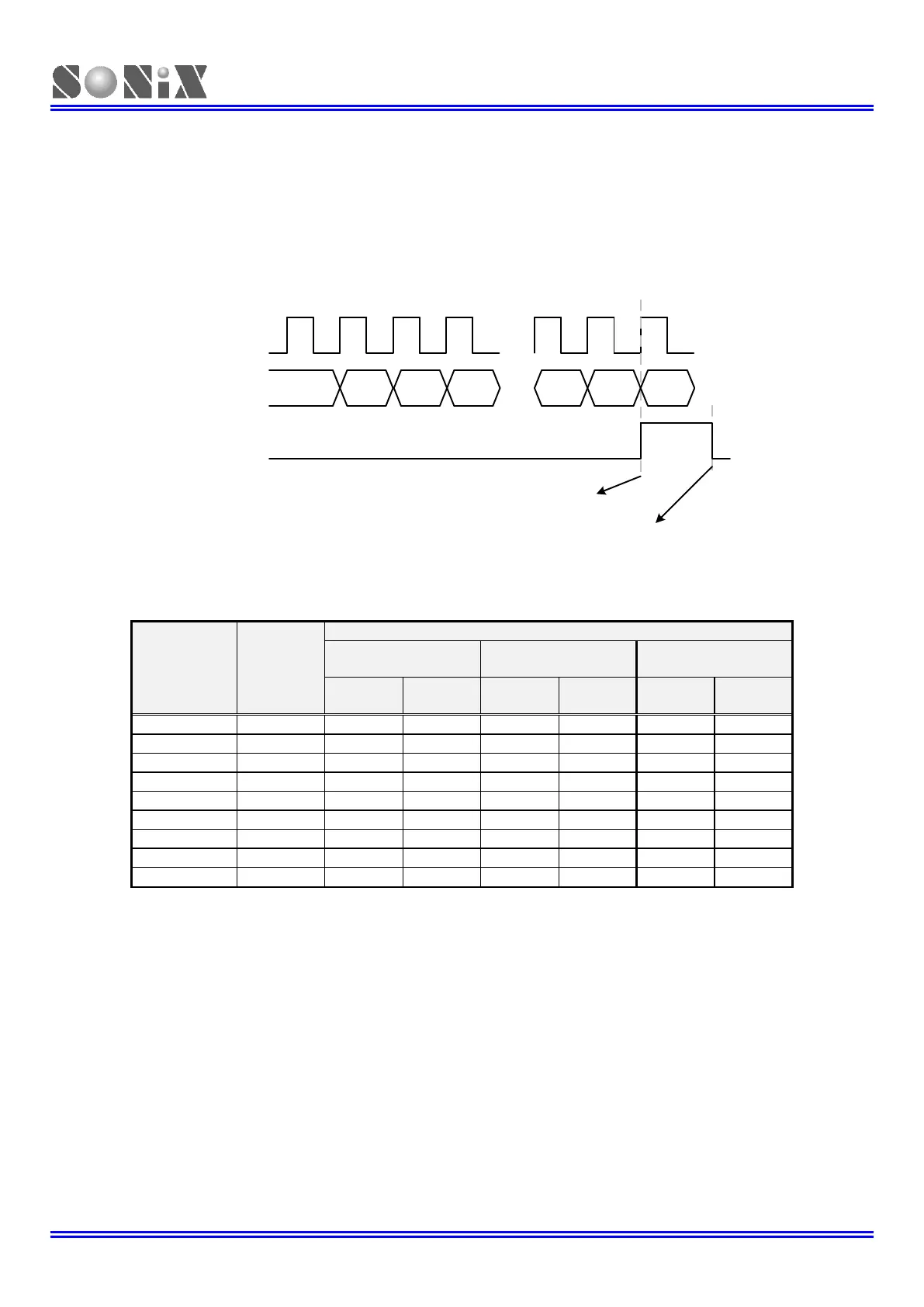
T0 timer is controlled by T0ENB bit. When T0ENB=0, T0 timer stops. When T0ENB=1, T0 timer starts to count. T0C
increases “1” by timer clock source. When T0 overflow event occurs, T0IRQ flag is set as ”1” to indicate overflow and
cleared by program. The overflow condition is T0C count from full scale (0xFF) to zero scale (0x00). T0 doesn’t build in
double buffer, so load T0C by program when T0 timer overflows to fix the correct interval time. If T0 timer interrupt
function is enabled (T0IEN=1), the system will execute interrupt procedure. The interrupt procedure is system program
counter points to interrupt vector (ORG 8) and executes interrupt service routine after T0 overflow occurrence. Clear
T0IRQ by program is necessary in interrupt procedure. T0 timer can works in normal mode, slow mode and green
mode. In green mode, T0 keeps counting, set T0IRQ and wakes up system when T0 timer overflows.
0x00 or “n”
by program
...
...
Clock
Source
T0C
T0IRQ
T0 timer overflows. T0IRQ set as “1”.
Reload T0C by program.
T0IRQ is cleared by program.
0x01
or n+1
0xFE 0xFF
...
...
0x00 or “n”
by program
0x02
or n+2
0x02
or n+2
T0 clock source is Fcpu (instruction cycle) through T0rate[2:0] pre-scaler to decide Fcpu/2~Fcpu/256. T0 length is 8-bit
(256 steps), and the one count period is each cycle of input clock.
Fhosc=16MHz,
Fcpu=Fhosc/4