2-4
BKM-120D/127W/129X/142HD
2-3-3. 3.58 f0 Adjustment
Note 1:ON/OFF of ACC should be performed with BKM-
127W menu of MAINTENANCE menu.
Note 2:The following adjustment menu is below the
BKM-127W menu of the MAINTENANCE menu.
F0
1. Turn OFF ACC.
2. Input the NTSC color bar signal.
3. Connect TP322 and TP321 (5V) of the BW board
using a jumper wire.
4. Connect the oscilloscope to TP421 of the BW board.
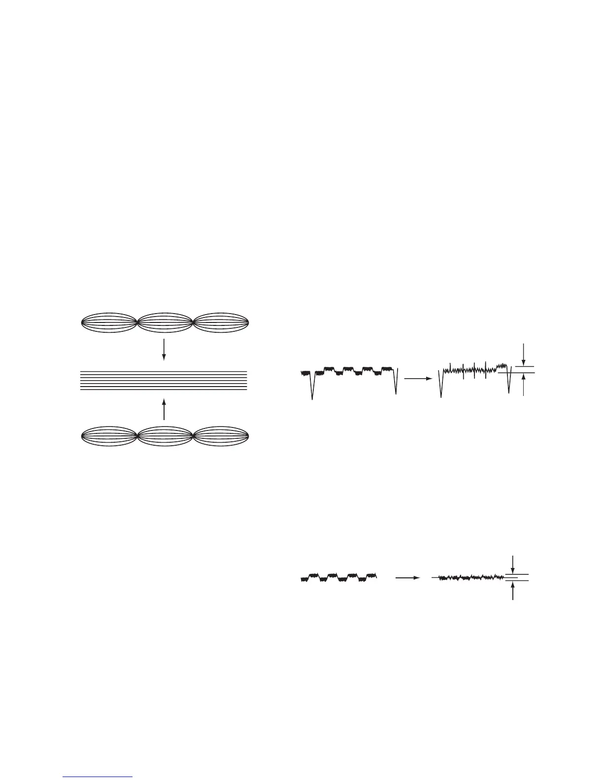
5. Adjust the F0 data so that the waveform stops or
moves slowly.
6. Turn ON ACC.
7. Disconnect the jumper wire.
Fig. 2-4.
2-3-4. Phase Adjustment
Note 1:ON/OFF of ACC should be performed with BKM-
127W menu of MAINTENANCE menu.
Note 2:The following adjustment menus are below the
BKM-127W menu of the MAINTENANCE menu.
SUB PHASE
ACC PHASE
R–Y PHASE
1. Input the NTSC color bar signal whose R–Y signal has
been turned off.
2. Turn OFF ACC.
3. Connect the oscilloscope to TP421 of the BW board.
4. Adjust the SUB PHASE data so that the TP421
waveform becomes flat.
5. Turn ON ACC.
6. Adjust the ACC PHASE data so that the TP421
waveform becomes flat.
TP421
Fig. 2-5.
7. Input the NTSC color bar signal whose R–Y signal has
been turned off.
8. Connect the oscilloscope to TP471 of the BW board.
9. Adjust the R–Y PHASE data so that the TP471
waveform becomes flat.
TP471
Fig. 2-6.
Below 10mV
H Period
Below 10mV