(j)
1-
z
w
~
1-
(j)
::::,
-,
0
-,:
.;
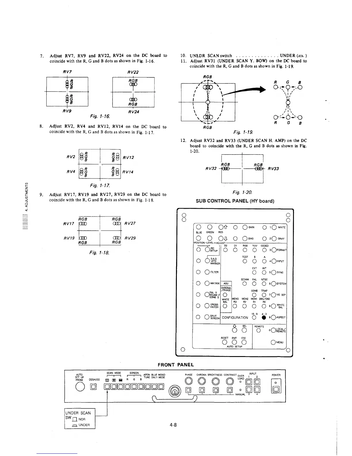
7.
8.
9.
Adjust RV7, RV9 and RV22, RV24 on the DC board
coincide with the R, G and B dots as shown in Fig. 1-16.
RVl
RV22
~
RGB
or
8
~
cJo
8
RGB
RV9
RV24
Fig. 1-16.
Adjust RV2, RV4
and RV12,
RV14 on the DC board
coincide with the R, G and B dots as shown in Fig. 1-17.
RV4 @i
Fig. 1-17.
i@ RV12
R~G
el RV14
to
to
Adjust RV17, RV19 and RV27, RV29 on the DC board to
coincide with the R, G and B dots as shown in Fig. 1-18.
RV17
e---1~
RV27
RV19
RGB I RGB
RV29
Fig. 1-18.
10.
UNE.DR SCAN switch
.............. UNDER (-=- )
11.
Adjust RV31 (UNDER SCAN Y. BOW) on the DC board to
coincide with the R, G and B dots as shown in Fig. 1-19.
RGB
R G
8
,
0~9~-D
I
I
' I
I
\:,'
I
~
I
I
I
\
I
/I\_
\ I
/ 6'
'
I
o:.. _:,-0
R
G
8
RGB
Fig. 1-19.
12. Adjust RV32 and RV33 (UNDER SCAN H. AMP) on the DC
board to coincide with the R, G and B dots as shown in Fig.
0
0
0
1-20.
RV32
RV33
Fig. 1-20.
SUB CONTROL PANEL (HY board)
0 0
011
0
QoAIN
0
1QWH1TE
BLUE
GREEN RED
0
0 O,0,
0
Qa1AS
0
2Q GRAY
POSITION -LEVEL-ADJUST
D1 RGB YUV
CODED
0
0
JO D2
o ~o
0 0
0
0 3OFORMAT
0 SAD.
TEST
B A
VlTC
0 0 0
4olNPUT
MARKER
EXT INT
0
QF!LTER
0
0
sQsYNC
SECAM PAL NTSC
-
0
OMA.TRIX ASU
0 0
o sQsYSTEM
CHROMA
/PHASE
COMB TRAP
0
o:~f
0
0
0 7QYC SEP
COMBS
MEM3 MEM2 M[Ml 065/D93
WHITE
BAL
R3 R2 RI
RC
0
0 CROSS
HATCH
0 0
0 0
0 aQWJ1rE
-
0
OSPUT
SCREEN
CONFIGURATION
16: 9
4: 3
0
• •OASPECT
8
SEL
REMOTE
0
0
oQ~~~~
RESET
ENT ESC
0 0 0
OMENU
AUTO SETUP
0
FRONT PANEL
AUTO
SET UP
PROBE
0
DEGAUSS
~
~
APER-BLUE MONO PHASE CHROMA BRIGHTNESS CONTRAST OVER INPUT
(Q] [I] !!! R G B TURE ONL 'I MODE O O
O
O
L';;'D [g] [g)
[g][g][g][g][g][g][g][g][g)
~
~
ij ij ij MA~UAL
~
~
(\
~
f)
UNDER SCAN
SWDNOR
.=. UNDER
-
4-8
POWER