Use
the
CCY
cables suppli
ed
with the TBC for the
co
nn
ect
ions
between the VTR and TBC. All the
other
input and
output
signal
con
ne
ctions emp
lo
y
BN
C connectors.
• Loop-through connectors are provided for Refe
ren
ce COMP
VIDEO, Reference SC, Reference COMP SYNC, and so when
this loop-through feature is employed,
turn
the
@,
@, @
75n
ON/OFF
swi
tc
hes
OFF.
In
other
uses,
turn
the switches
ON.
•
By
selecting
the
@ NON COMP/COMP switch, the @
VIDE0-3
output
can be turned in
to
composite video or
non-composite video.
• Reference COMP VIDEO, Reference SC,
or
COMP SYNC is
required to
ge
n lock the TBC
to
the
external reference signal.
Sel
ect
the REFERENCE SELECT switch OQ the SYNC
GENERATOR 1
bo
ard to l
oc
k at REFERENCE VIDEO
or
at
REFERENCE SYNC.
A sufficiently low time base error is required for the
ge
n-lock
signal
s,
and if this error is high, the proper
11erfo
rmance
of
the
BVT-2000 will n
ot
be disp
la
ye
d.
When the
sig
nal is
no
t conn
ec
ted to the reference input,
the
sync
ge
nera
tor
inside the BVT-2000 au
tomat
ically becomes the
reference.
When using the sync generator inside the BVT-2000
to
generate
the reference signal, its frequency stabili
ty
is determined by the
crystal oscillator
on
the
SYNC GENERA TOR 1 printed circuit
board. For normal use the stab
il
ity
is
about
30 ppm across a
temperature range
of
0°C
to
40
°
C.
If
this is n
ot
suffici
en
t for the
intended operation, replace the crystal oscillator with a
unit
having
th
e required stab
ili
ty
or app
ly
a stable reference signal
from an external source.
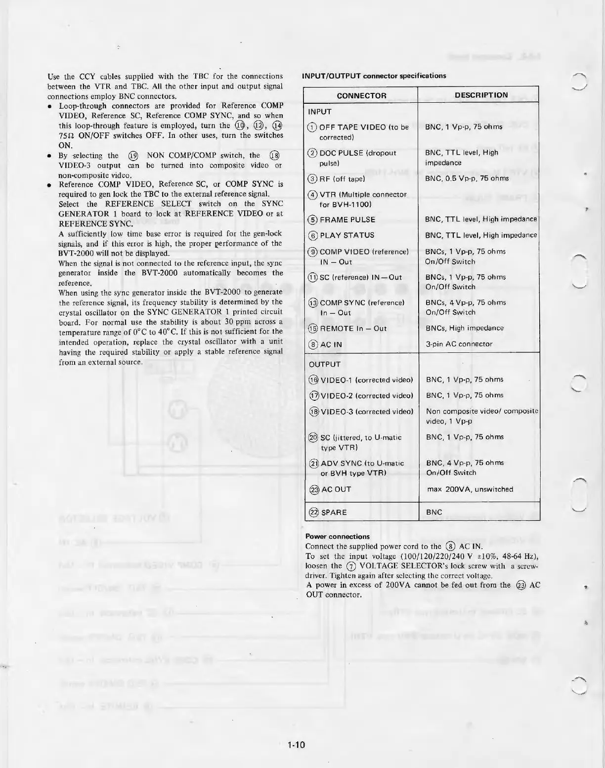
INPUT
/OUTPUT
connector
specifications
1-10
CONNECTOR
DESCRIPTION
INPUT
CD
OFF
TAPE
VIDEO
(to
be
BNC, 1
Vp
-p,
75
ohms
corrected)
(3)
DOC
PULSE
(dropout
BNC,
TTL
level, High
pulse)
impedance
@R
F
(off
tape)
BNC, 0.5
Vp-p,
75 ohms
@)
VTR
(Multiple
connect
or
for
BVH-1100)
@
FRAME
PULSE
BNC,
TTL
level, High impedance
@
PLAY
STATUS
BNC,
TTL
level, High impedance
@COM
P
VIDEO
(reference)
BNC
s,
1
Vp-p,
75
ohms
IN
-
Out
On/Off
Switch
@sc
(referer.ice)
IN
-O
ut
BNCs, 1
Vp-p,
75
ohms
On/Off
Switch
@COM
P
SYNC
(reference)
BNCs, 4
Vp·p,
75
ohms
In
-
Out
On/Off
Switch
@R
EMOTE
In
-
Out
BNCs, High
imp
edance
@
ACIN
3-pin
AC
connector
OUTPUT
@
VIDE0-1
(corr
ec
ted
video
)
BNC, 1
Vp-p,
75 ohms
@
VIDE0
-2 (corrected video)
BNC, 1
Vp-p,
75 ohms
@
VIDE0-3
(corr
e
cted
video)
Non com
po
si
te
video/
composite
video, 1
Vp-p
@SC
(jitt
ered,
to
U-m
atic
BNC, 1
Vp-p,
75
ohms
type
VTR)
@
ADV
SYNC
(to
U-m
atic
BNC, 4
Vp-p,
75
ohms
or
BVH
type
VTR)
On/Off
Sw
itch
@
AC
OUT
max
200VA,
unswitched
@ SPARE
BNC
Power
connections
Connect the supp
li
ed power cord
to
the @
AC
I
N.
To set the input voltage (100/120
/22
0
/2
40 V ±10%, 48-
64
Hz),
loosen
th
e
Ci)
VOLTAGE SELECTOR's lock screw with a screw-
dr
iver. Tight
en
aga
in
af
ter
se
lecting the correct voltage.
A power in excess
of
200VA cann
ot
be
fed
ou
t from the @
AC
OUT connecto
r.