r
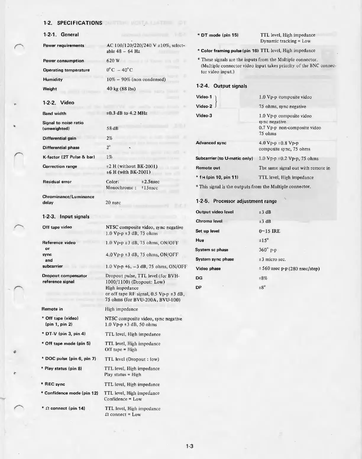
1-2. SPECIFICATIONS
1-2-1. General
Power requirements
Power consumption
Operating
temperature
Humidity
Weight
1-2-2. Video
Band
width
Signal
to
noise ratio
(unweighted)
Differential gain
Differential phase
K-factor (2T Pulse
& bar)
Correction range
Residual error
Chrominance/Luminance
delay
1-2-3. Input signals
Off
tape
video
Reference video
or
sync
and
subcarrier
Dropout compensator
reference signal
Remote in
* Off
tape
(video)
(pin 1, pin 2)
* DT-V (pin
3,
pin 4)
* Off tape mode (pin 5)
* DOC pulse (pin
6,
pin
7)
* Play
status
(pin 8)
*REC
sync
* Confidence mode (pin 12)
*
n
connect
(pin 14)
AC
100
/
120
/22
0
/24
0 V ±
10
%, select·
able
48
- 64 Hz
620W
0°C -
40
°C
10% -
90
% (non condensed)
40
kg (88 lbs)
±0.3 dB to
4.2
MHz
58dB
2%
20
1%
±2 H (without BK-2001)
±6
H
(with
BK-2001)
Color:
±2.5nsec
Monochrome : ±
15n
scc
20 nsec
NTSC
composite
video, sync negati
ve
1
.0
Vp-p
±3
dB, 75 ohms
1.0 Vp-p ±3 dB,
75
oh
ms
,
ON/OFF
4.0Vp-
p ±3 dB,
75
ohms,
ON/Off
1.0 Vp-p +6,
-3
dB, 75 ohms, ON/OJ:F
Dropout pulse,
TTL
level (for BVH-
1000/1100) (Dropout: Low)
Hi
gh impedance
or
off tape
Rr
signal, 0.5 Vp-p
±3
dB,
75 ohms (for BVU-200A, BVU-100)
High impedance
NTSC
com
posite video, sync negati
ve
1.0 Vp-p ±3 dB, 50 ohms
TTL
level,
Hi
gh impedance
TTL
level, High
im
pe
dance
Off
t
ape
=
Hi
gh
TTL
level
(Dropout
: low)
TTL
level, High impedance
Pla
y status =
Hi
gh
TT
L level,
Hi
gh impedance
TTL
level, Hi
gh
impe
da
nce
Confidence = Low
TTL
level, High impedance
n conn
ect
= Low
1-
3
*OT
mode (pin 15)
TTL
level,
Hi
gh impedance
Dynamic trackin
g=
L
ow
*Color
framing pulse (pin 16) TTL level,
Hi
gh impedan
ce
* The
se
signa
ls
are
th
e inputs from
the
Multiple connector.
(Multiple
co
nnec
tor
vid
eo
input
takes priority
of
the
BN
C connec-
tor
v
id
eo input.)
1-2-4.
Output
signals
Video-1 }
Video-2
Video-3
Advanced sync
1.0 Vp-p co
mpo
site video
75 ohms,
sy
nc negative
1.0 Vp-p
com
posite v
id
eo
sy
nc
ne
gat
iv
e
0.7 Vp-p non-composite video
75
ohms
4.0 Vp-p ±0.8 Vp-p
composite syn
c,
75 ohms
Subcarrier (to U-matic only) 1.0 Vp-p ±0.2 Vp-p,
75
ohms
Remote
out
The same signal
ou
t with remote
in
*
fH
(pin 10, pin 11)
TTL le
ve
l,
Hi
gh impedance
*This s
ig
na
l is
the
output
s from the Multiple connector.
1-2-5. Processor adjustment range
Output
video level
Chroma level
Set
up level
Hue
System sc phase
System sync phase
Video phase
DG
DP
±3
dB
±3
dB
0- 15
IR
E
±
15
°
360° p-p
± 3 micro sec.
±
560
nsec p-p (280 nse
c/s
tep)
±8
%
±8
0