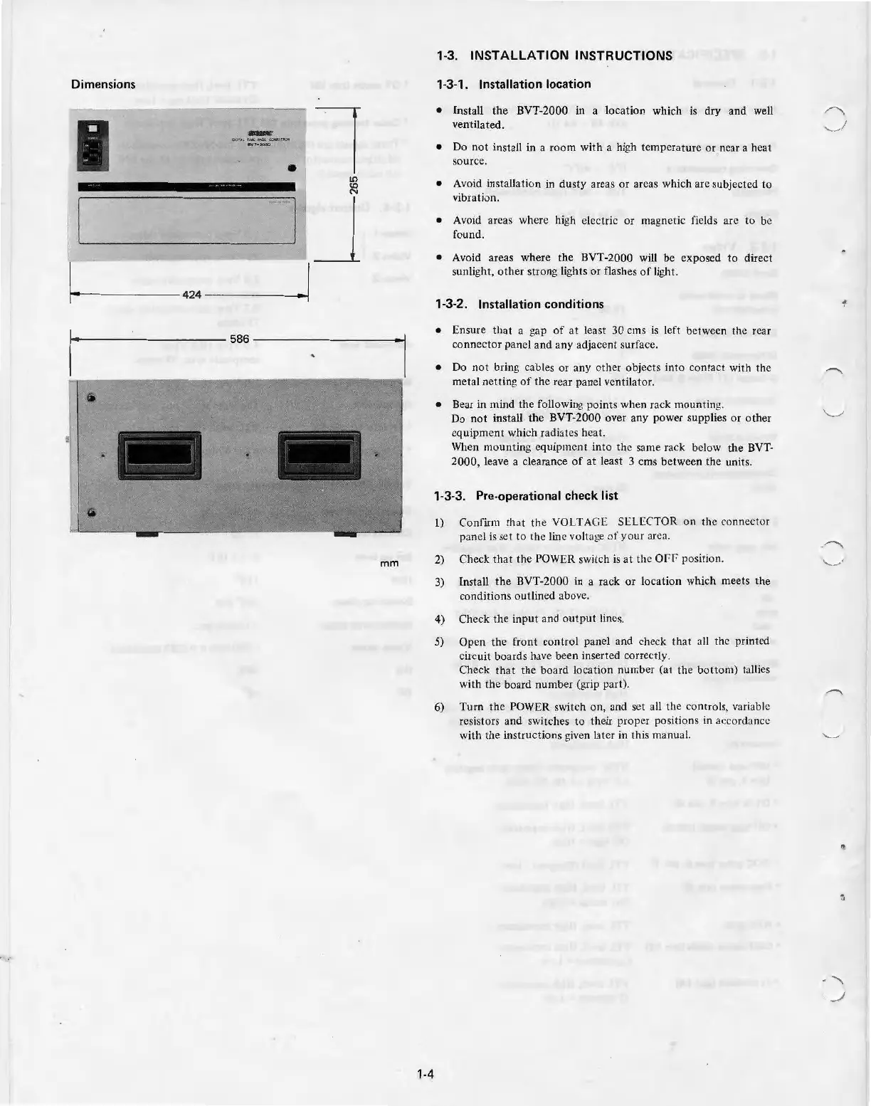
Dimensions
•
l
LO
<O
N
1
-----
'J
r------------1
-
-42
4
__
[
mm
1·4
1·3. INSTALLATION INSTRUCTIONS
1·3·1 .
Installation location
•
Install
the
BVT-2000
in
a l
ocat
ion which
is
dry and well
ventilated.
• Do
not
install
in
a
room
with a
hi
gh
temperature or near a heat
source .
• Avoid installation in
dusty
areas
or
areas which are subjected to
vibration.
• Avoid areas where high electric
or
magnetic fields
arc
to
be
found.
• Avoid areas where
the
BVT-
2000
will be exposed
to
direct
sun
li
g
ht
,
other
strong
li
ghts
or flashes
of
light.
1-3-2. Installation conditions
• Ensure that a gap
of
at
least
30
ems is left between the rear
co
nn
ector
panel
and
any adjacent surface.
• Do not bring cables
or
any
othe
r objects
into
contac
t
wi
th the
metal netting
of
the rear panel ventilator.
• Bear in mind
the
following
po
int
s when rack mounting.
Do
not
install the BVT-2000 over any power supplies
or
other
equipment
which radiates heat.
When mounting equipment into
the
same
rack below
the
BVT-
2000,
leave a clearance of
at
least 3 ems between the units.
1·3·3. Pre·operational check list
J) Confirm
that
t
he
VOLTAGE
SE
LECTOR
on
the connector
panel
is
set
to th
e line volta
ge
of
your
area.
2)
Check
that
the
POWER switch
is
at
the
Of
f'
positi
on
.
3) Insta
ll
the
BVT-2000 in a rack
or
l
ocation
whi
ch
meets
the
con
di
tions
outlined above.
4)
Check
the
input
and o
utput
lines.
5)
Open the front control panel and check that all the prin
te
d
circuit boards have been inserted correctly.
Check th
at
the
board location number (at
the
bottom)
ta
ll
ies
with
the
board n
um
ber (grip part).
6)
Turn
the POWER switch
on,
and
set all the controls, variable
resistors
and
sw
itches
to
their proper positions in accordance
with the instructions given later in this manual.