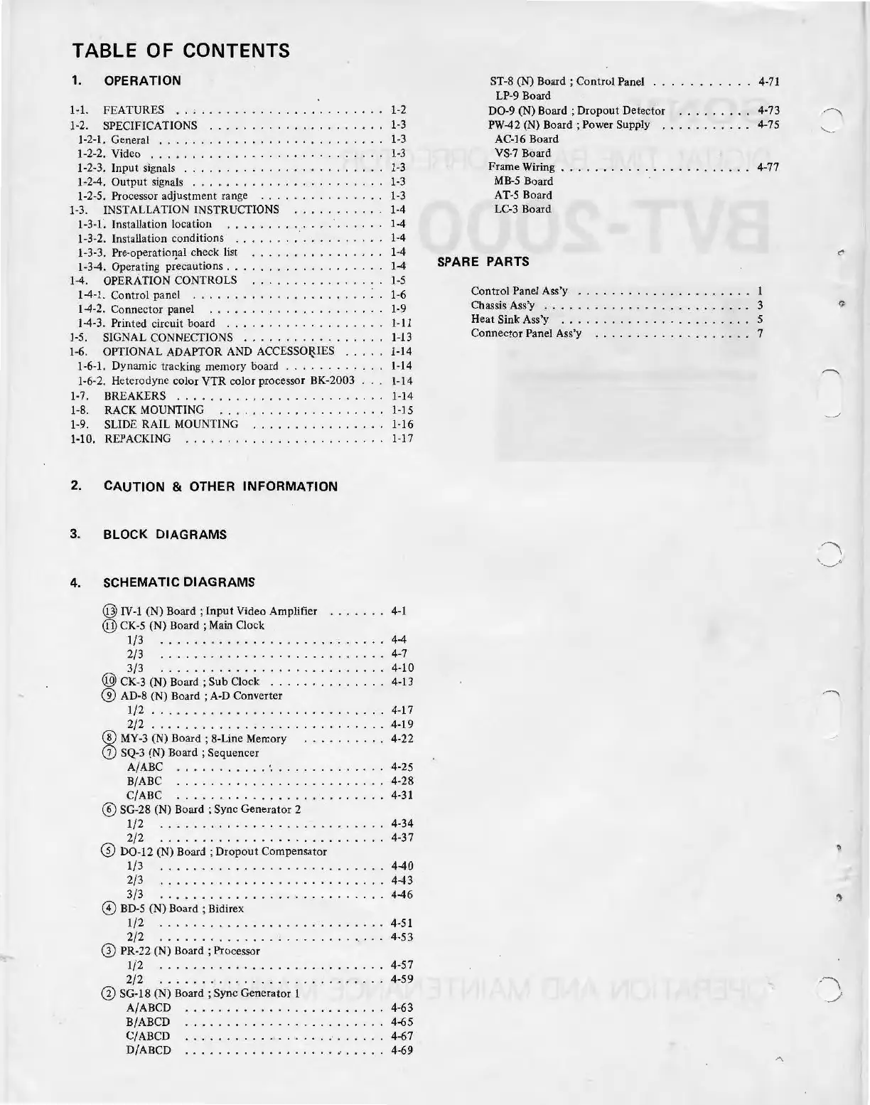
TABLE OF CONTENTS
1.
1-1.
1-2.
OPERATION
FEATURES
..
,
......................
1-
2
SPECIFICATIONS
..
...................
1-
3
1-2-1. General . . . . . . . . . . . . . . . . . . . . . . . . . . .
1-2-2. Video . . . . . . . . . . . . . . . . . . . . . . . . . . . .
1-
3
1
-3
1-
3
1
-3
1-3
1-2-3.
In
put signals
................
. . .
....
.
1-2-4.
Output
signals
...
.
..................
.
1-2-5. Processor adjustment range
..............
.
1-3
. INSTALLATION INSTRUCTIONS
..........
.
1-4
1-
3-1. Installation location
1-4
1-3-2. Installation conditions . . . . . . . . . . . . . . . . . .
1-4
1-3-3. Pre-operatioIJal check list . . . . . . . . . . . . . . . .
1-4
1-3-4. Operating precautions
....
.......
.....
...
1-4
1-4. OPERATION CONTROLS
..............
..
1
-5
1-4-1. Control panel
.....................
: .
1-6
1-4-2. Connector panel . . . . . . . . . . . . . . . . . . . . . 1-9
1-4-3. Printed circuit board
...................
1-1
1
1-5.
SIGNAL CONNECTIONS
.................
1-13
1-6.
OPTIONAL ADAPTOR AND
ACCESSO~IES
.....
I-14
1·6·1. Dynamic tracking memory board
............
1-14
1-6-
2. Heterodyne color
VTR
color processor
BK
-2003 . . . 1-14
1-7. BREAKERS
........................
. 1-14
1-8. RACK MOUNTING
....................
1-15
1-9
. SLIDE RAIL MOUNTING
............
.. ..
l-I
6
1·10. REPACKI
NG
........................
1-17
2. CAUTION & OTHER
INFORMATION
3. BLOCK DIAGRAMS
4. SCHEMATIC DIAGRAMS
@ I
V-1
(N) Board ;
In
put
Video Amplifier
.......
4-1
@
CK
-5 (N) Board ; Main Cl
ock
1
/3
..
.
...........
.
.....
. .
.....
4-4
2/3
..
.
.......
.
................
4
-7
3/3
...................
.
.......
4-10
@ CK-3 (N) Board ;
Sub
Clock
........
.
.....
4
-1
3
@ AD-8 (N) Board ; A-D Converter
1/2
...
.
...
. .
...................
4-17
2/ 2
............................
4-19
®
MY-3
(N) Board ; 8-Line Memory
..
.
.....
. . 4-22
(j) SQ-3 (N) Board ; Sequencer
A/
AB
C . . . . . .
.....
._
. . . . . . . . . . . . . 4-25
B/ABC
........
.
.......
......
...
4-28
C/ABC
........
........
........
. 4-31
@ SG-28 (N) Board ; Sync Generator 2
1
/2
...........................
4-34
2
/2
..........
...
..
. . .
.........
4-37
@
D0-12
(N)
Board;
Dropout Compensator
1/3
............
.
..
. .
..
...
.....
4-40
2
/3
.................
. .
........
4-43
3/3
.
...
.
..
.
......
.
............
4-46
©
BD-5
(N) Board ; Bidirex
1/2
...............
. .
..........
4-51
2/2
....
..
.....
.
.....
......
....
4-53
G)
PR-22 (N) Board ; Processor
1/2
.......................
.
...
4-57
2/2
...........
...............
. 4-59
Q)
SG-18 (N) B
oard;
Sync Generator 1
A/ABCD
...........
.
.........
...
4-63
B/ABCD
.........
.
.....
.
........
4-65
C/ABCD .
...
.......
....
.........
4-67
D/ABCD
..............
.
...
.. .
..
..
4-69
ST-8 (N) Board ; Control Panel
....
.......
4-71
LP-9 Board
D0-9
(N)
Board;
Dropout Detector
........
. 4-73
PW-42 (N)
Board;
Power Supply .
..
.
.......
4-75
AC-16 Board
VS-7
Board
Frame Wiring . . . . . . . . . . . . . . . . . . . . . . . 4-77
MB-5
Board
AT-5 Board
LC-3
Board
SPARE PARTS
Control Panel
As
s'y . . . . . . . . . . . . . . . . . . . . . 1
Chassis Ass'y . . . . . . . . . . . . . . . . . . . . . . . . . 3
Heat Sink Ass'y
.......................
5
Connector Panel Ass'y
...
...
..
..
.
..
.
.....
7