c
"
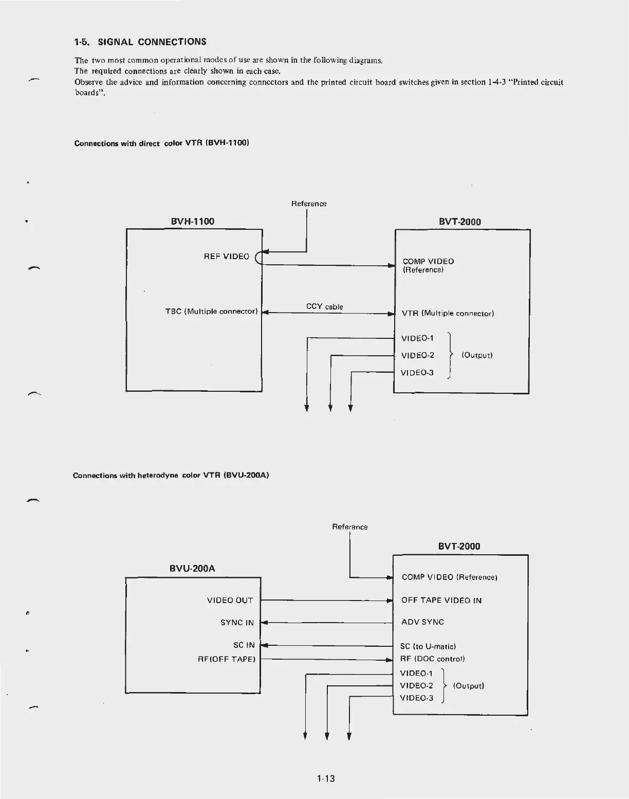
1·5. SIGNAL CONNECTIONS
The two most common operational modes
of
use are shown in the following diagrams.
The required connections are clearly shown in each case.
Observe the advice and information concerning connectors and the printed c
ir
cuit board switches given in secti
on
1-4
-3
"Printed circuit
boards".
Connec
tions
with
direct
color
VTR
(BVH-1100)
Reference
BVH-1100
BVT-2000
~
REF
VIDEO
(
COMP
VIDEO
(Referen
ce
)
TBC
(Mult
iple connector)
CCV cable
-
VTR
(M
ult
ip
le connector)
VIDE0
-1
}
V
ID
E0-2
(Output)
V
IDE
0-3
, ,
Connections
with
he
terodyn
e
color
VTR
(BVU
-
200A)
Reference
BVT
-2000
BVU-200A
- COMP V IDEO (Reference)
V I
DEO
OUT
OFF
TAPE
VIDEO IN
SY
NC IN
ADV
SYNC
SC
IN
-
SC
(to
U-matic)
RF(OFF
TAPE)
RF
(DOC
control)
V
ID
E0-
1 }
V
IDE
0-2
(Output)
V
ID
E0-3
.
,.
1-13