3-27
MVS-8000 System
SYSTEM SETUP
Setup example : For the system
33
33
3
System : MVS-8000 x 1 unit, router x 1 unit (8 x 4)
1. Connect Destination 1 (virtual No. 5) of a router to Primary 1 (virtual No. 19) of the MVS-8000.
2. Connect Destinations 2 to 4 (virtual No. 6 to 8) of a router to Primary 2 to 4 (virtual No. 20 to 23) of
the MVS-8000.
Page 7363
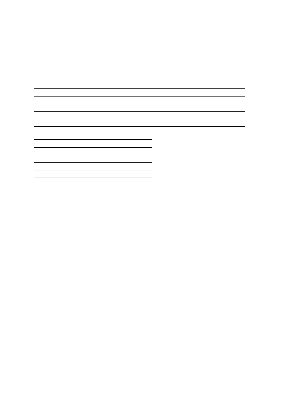
Wiring# Destination Level Source Level
1 5 RTR1
*
1 19 SWR1
*
1
2 6 RTR2
*
1 20 SWR2
*
1
3 7 RTR3
*
1 21 SWR3
*
1
4 8 RTR4
*
1 22 SWR4
*
1
* : The Source/Destination Names that are set from the Router/MVS side are displayed.
Virtual destination number Virtual source number
519
620
721
822
Connection information
3-7. Tally Setup
 Loading...


