– 68 –
SECTION 7
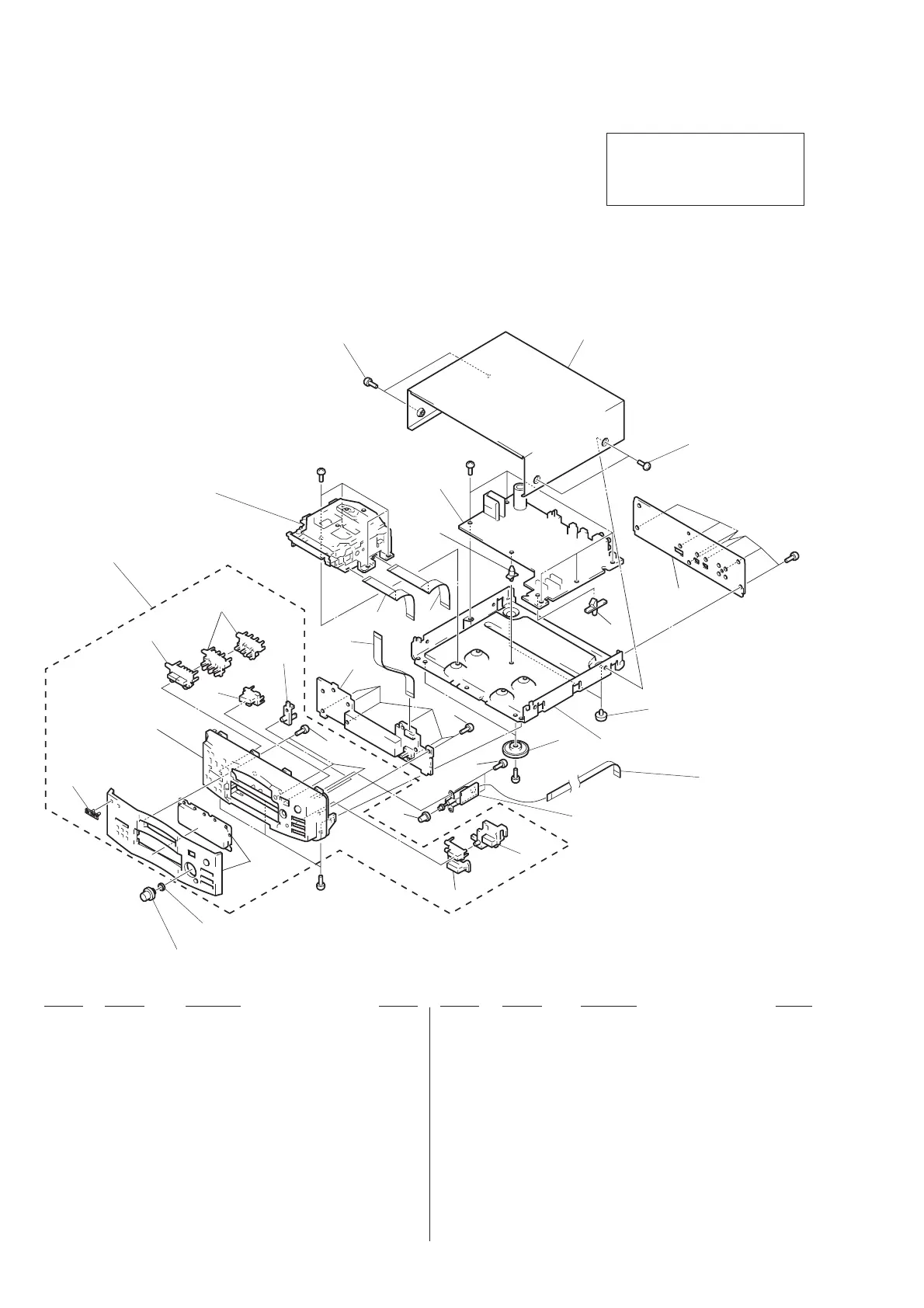
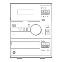
EXPLODED VIEWS
1 X-4947-652-1 PANEL ASSY, FRONT
2 4-962-708-01 EMBLEM (4-A), SONY
3 4-985-889-01 BUTTON (REC) (CD SYNC, r REC)
4 4-985-890-01 BUTTON (MODE)
5 4-985-891-01 BUTTON (EJECT) (§ EJECT)
6 4-985-894-01 BUTTON (EDIT)
7 X-4947-763-1 BUTTON (F/R) ASSY (0, ))
8 4-985-892-01 BUTTON (PLAY) (fl, p)
* 9 A-4699-657-A PANEL BOARD, COMPLETE
10 1-777-654-11 WIRE (FLAT TYPE) (19 CORE)
11 1-777-558-11 WIRE (FLAT TYPE) (19 CORE)
12 1-777-559-11 WIRE (FLAT TYPE) (29 CORE)
* 13 A-4699-656-A MAIN BOARD, COMPLETE
Ref. No. Part No. Description Remark
Ref. No. Part No. Description Remark
14 3-363-099-01 SCREW (CASE 3 TP2)
* 15 4-985-899-11 CASE
* 16 4-985-898-12 PANEL (MDS), BACK
* 17 3-350-847-21 HOLDER, PCB
18 4-965-822-01 FOOT
19 4-977-699-11 LEG (F)
20 1-777-473-11 WIRE (FLAT TYPE) (5 CORE)
21 4-951-620-01 SCREW (2.6X8), +BVTP
* 22 1-663-192-11 REC VOL BOARD
23 4-985-896-01 KNOB (REC)
24 4-985-925-01 KNOB (JOG)
25 4-988-161-01 SPRING, RING
3
1
2
7
6
5
8
25
not
supplied
not supplied
23
20
22
21
21
21
#1
#1
#6
#6
#1
16
15
14
13
not
supplied
14
18
not supplied
19
11
12
10
9
4
17
24
MDM-3A
NOTE:
• -XX and -X mean standardized parts, so they
may have some difference from the original
one.
• Color Indication of Appearance Parts Example:
KNOB, BALANCE (WHITE) . . . (RED)
↑↑
Parts Color Cabinet’s Color
• Items marked “∗” are not stocked since they
are seldom required for routine service. Some
delay should be anticipated when ordering
these items.
• The mechanical parts with no reference num-
ber in the exploded views are not supplied.
• Hardware (# mark) list is given in the last of
the electrical parts list.
The components identified by mark
! or dotted line with mark ! are
critical for safety.
Replace only with part number
specified.
(1) CHASSIS SECTION