Do you have a question about the Sony CDX-4250 and is the answer not in the manual?
Details on power output and total harmonic distortion for the unit.
Technical details for CD player, tuner, and power amplifier sections.
Model name, power requirements, dimensions, and supplied accessories.
Guidelines for handling optical pick-ups, laser diodes, and flexible boards.
Critical component replacement and safety-related component warnings.
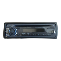
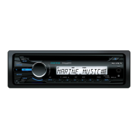
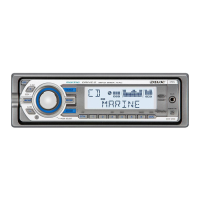
Identification of unit controls and display elements.
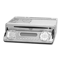
Initial setup, unit reset, and front panel detachment/attachment procedures.
Procedure for setting the 12-hour digital clock.
Instructions for listening to CDs, track locating, and playback modes.
Procedures for memorizing and tuning radio stations.
Adjusting bass, treble, balance, fader, and sound characteristics.
Using the D-Bass feature for boosted bass and controlling beep sounds.
Important notes on operating conditions, connections, and dealer consultation.
Guidance on fuse replacement, connector cleaning, and unit removal.
Important safety, accessory position, and reset guidelines for unit connection.
Visual guide for connecting the unit to car power and speakers.
Steps to remove the unit's cover and front panel assemblies.
Procedure for removing the display board.
Steps to remove the CD mechanism block.
Procedures for removing the main board and heat sink.
Procedure for removing the chassis (T) sub assembly.
Steps to detach the lever assembly components.
Procedure for removing the servo board.
Steps to detach the roller assembly.
Procedure for removing chassis (OP)/(O/S) assembly.
Steps to detach the optical pick-up block.
Procedures for adjusting FM/AM tuner sensitivity and center frequency.
Detailed steps for FM center, SENS/IF, and AM sensitivity.
Procedure to adjust focus bias on the servo board for clear waveforms.
Coarse adjustment for optical pick-up gain.
Detailed pinout information for IC801 (System Control).
Diagram showing the layout of internal circuit boards.
Illustrations of signal waveforms for key test points.
Printed wiring diagrams for servo and pick-up flexible boards.
Detailed schematic diagram for the CD mechanism section.
Printed wiring diagrams for the display board, sides A and B.
Detailed schematic diagram for the display section.
Printed wiring diagram for the main board.
Detailed schematic diagram for the main section, part 1.
Block diagrams illustrating the internal functions of key ICs.
Exploded view of the chassis assembly and related parts.
Exploded view of the front panel assembly and its components.
Exploded view of the CD mechanism assembly, part 1.
Exploded view of the CD mechanism assembly, part 2.
Exploded view of the CD mechanism assembly, part 3.
Lists of parts for disc-in, display boards, and semiconductors.
Lists of capacitors and resistors used in the unit.
Lists of tuner, connector, IC, and vibrator components.
Lists of servo board parts, miscellaneous items, and accessories.
| Preset Stations | 30 |
|---|---|
| RMS Power Output | 17 Watts x 4 Channels |
| CD Player | Yes |
| CD-R/RW Playback | Yes |
| MP3 Playback | Yes |
| WMA Playback | Yes |
| Display Type | LCD |
| Detachable Faceplate | Yes |
| Remote Control | Yes |
| AUX Input | Yes |
| USB Port | No |
| Bluetooth | No |
| iPod Compatibility | No |
| Channels | 4 |
| Tuner Bands | AM, FM |