CFD-20/30
SAFETY
CHECK-OUT
TABLE
OF
CONTENTS
After
correcting
the
original
service
problem,
perform
the
following
safety
check
before
releasing
Section
Titile
Page
the
set
to
the
customer:
Check
the
antenna
terminals,
metal
trim,
“‘metallized”’
SECTION
1.
SERVICING
NOTES
------+--s--reesssssseeeeee
3
knobs,
screws,
and
all
other
exposed
metal
parts
for
SECTION
2.
GENERAL
----:-eecssccessssssscnscscesssesssseenseseneuns
4
AC
leakage.
Check
leakage
as
described
below.
;
SECTION
3.
DISASSEMBLY
ov-e-seosescesceseesccseecsarsssseeores
6
LEAKAGE
TEST
SECTION
4.
MECHANICAL
ADJUSTMENT
---------------
10
The
AC
leakage
from
any
exposed
metal
part
to
SECTION
5.
ELECTRICAL
ADJUSTMENT
-.----.---------
10
earth
ground
and
from
all
exposed
metal
parts
to
any
exposed
metal
part
having
a
return
to
chassis,
must
SECTION
6.
DIAGRAMS
not
exceed
0.5
mA
(500
microampers).
Leakage
6-1.
Block
Diagramss++++++++ss+-secssssesseessseneeessesessteenetsnuneess
19
current
can
be
measured
by
any
one
of
three
6-2.
Circuit
Boards
Location
seeccecsssssse+eeeeseseeesenseenenertenees
23
methods.
6-3.
Printed
Wiring
Boards-----+-r++r+sssesseessersessensenneeneveeens
24
1.
A
commercial
leakage
tester,
such
as
the
6-4.
Schematic
Diagrams
—
Audio
Section—
-vsresserereeseees
27
Simpson
229
or
RCA
WT-S40A.
Follow
the
6-5.
Semiconductor
Lead
Layouts
:
manufacturers’
instructions
to
use
these
instru-
aC:
Binck
Dingrms
Se
coee
ae
roodaien
ments.
6-6.
Schematic
Diagrams
—CD
Section—
crrrersrrsersereessneeee
31
2.
A
battery-operated
AC
milliammeter.
The
Data
63
Scucgialie
Tages
Taner
Sola
wei
edeoiae
45
Precision
245
digital
multimeter
is
suitable
for
this
job.
SECTION
7.
EXPLODED
VIEWS
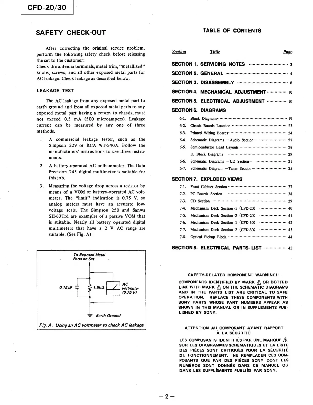
3.
Measuring
the
voltage
drop
across
a
resistor
by
7-1,
Front
Cabinet
Section
ser+sssserrscessesseeversseeeesvecssereessese
37
means
of
a
VOM
or
battery-operated
AC
volt-
12.
PC
Roatds
‘Séstion..
-sesteshdswsasieusarctdacaninaaias
38
meter.
The
‘limit’
indication
is
0.75
V,
so
analog
meters
must
have
an
accurate
low-
voltage
scale.
The
Simpson
250
and
Sanwa
7-3.
CD
Section
cevrsrereessssscssessesssavnenseens
evsiveiecesseaetsd
+
39
7-4,
Mechanism
Deck
Section
-1
(CFD-20)
SH-63Trd
are
examples
of
a
passive
VOM
that
7-5.
Mechanism
Deck
Section
-2
(CFD-20)
is
suitable.
Nearly
all
battery
operated
digital
7-6.
Mechanism
Deck
Section
-1
(CFD-30)
multimeters
that
have
a
2
V
AC
range
are
7-1.
Mechanism
Deck
Section
-2
(CFD-30)
suitable.
(See
Fig.
A)
7-8.
Optical
Pickup
Black
3am
aindnconmotuintintae
44
SECTION
8.
ELECTRICAL
PARTS.
LIST
-+-+---+-:-++++
45
To
Exposed
Metal
Parts
on
Set
SAFETY-RELATED
COMPONENT
WARNING!!
AC
voltmeter
|_|
(0.75
Vv)
=
Earth
Ground
Using
an
AC
voltmeter
to
check
AC
leakage.
COMPONENTS
IDENTIFIED
BY
MARK
A
OR
DOTTED
LINE
WITH
MARK
A
ON
THE
SCHEMATIC
DIAGRAMS
AND
IN
THE
PARTS
LIST
ARE
CRITICAL
TO
SAFE
OPERATION.
REPLACE
THESE
COMPONENTS
WITH
SONY
PARTS
WHOSE
PART
NUMBERS
APPEAR
AS
SHOWN
IN
THIS
MANUAL
OR
IN
SUPPLEMENTS
PUB-
LISHED
BY
SONY.
ATTENTION
AU
COMPOSANT
AYANT
RAPPORT
A
LA
SECURITE!
LES
COMPOSANTS
IDENTIFIES
PAR
UNE
MARQUE
/\
SUR
LES
DIAGRAMMES
SCHEMATIQUES
ET
LA
LISTE
DES
PIECES
SONT
CRITIQUES
POUR
LA
SECURITE
DE
FONCTIONNEMENT.
NE
REMPLACER
CES
COM-
POSANTS
QUE
PAR
DES
PIECES
SONY
DONT
LES
NUMEROS
SONT
DONNES
DANS
CE
MANUEL
OU
DANS
LES
SUPPLEMENTS
PUBLIES
PAR
SONY.