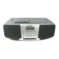
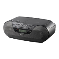
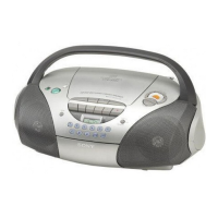
CFD-S45L/S47L
– 23 – – 24 –
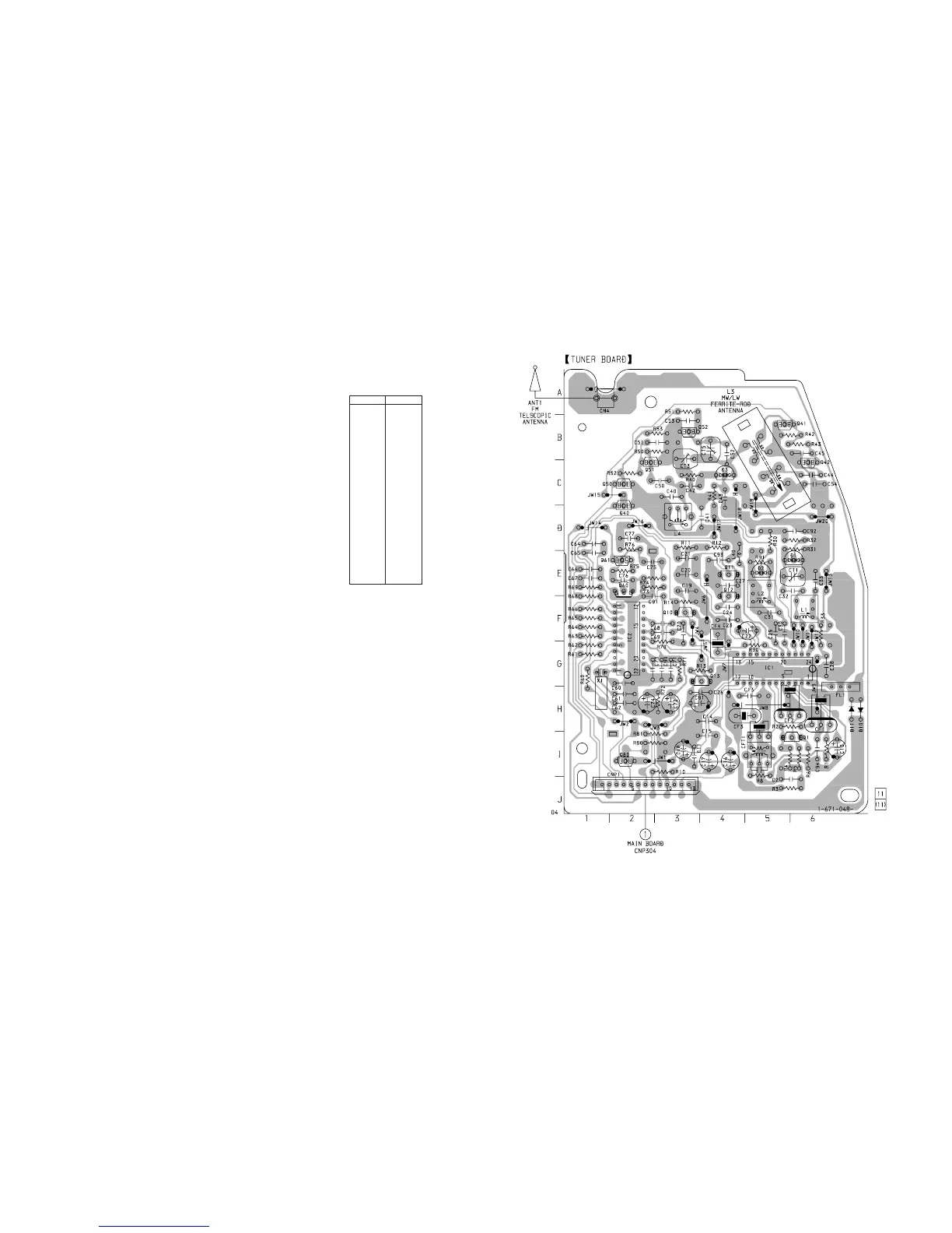
5-5. PRINTED WIRING BOARD — TUNER SECTION — • Refer to page 18 for Circuit Boards Location.
D1 E-6
D2 E-5
D3 C-4
D10 H-6
D11 H-6
IC1 G-5
IC2 F-2
Q1 I-6
Q10 F-3
Q11 E-4
Q12 F-4
Q13 G-4
Q40 D-2
Q41 B-5
Q42 C-6
Q50 C-2
Q51 C-2
Q52 B-3
Q60 E-2
Q61 E-2
Q80 I-2
• Semiconductor
Location
Ref. No. Location
Note on Schematic Diagram:
• All capacitors are in µF unless otherwise noted. pF: µµF
50 WV or less are not indicated except for electrolytics
and tantalums.
• All resistors are in Ω and
1
/
4
W or less unless otherwise
specified.
•
¢
: internal component.
• U : B+ Line.
• Voltage is dc with respect to ground under no-signal
(detuned) condition.
no mark : FM
( ) : MW
<>: LW
• Voltages are taken with a VOM (Input impedance 10 MΩ).
Voltage variations may be noted due to normal produc-
tion tolerances.
• Signal path.
F : FM
f : MW/LW
Note on Printed Wiring Boards:
• X : parts extracted from the component side.
• b : Pattern from the side which enables seeing.
(Page 34)



 To Next Page