2-24
DCR-PC103E/PC104E/PC105/PC105E
Note: When the flash error code (E: 91: **) is displayed. After completion of “VTR check”,
clear the error flag in the following method.
(To eject a cassette, connect
the control switch block.
(PS4400))
VC-
319
AC IN
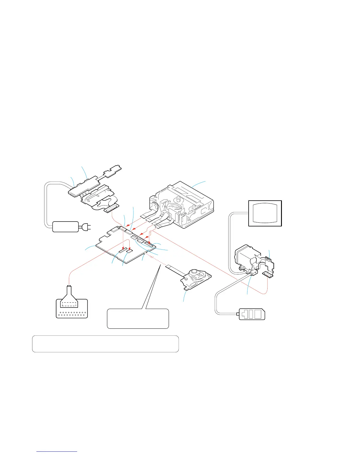
[SERVICE POSITION TO CHECK THE VTR SECTION]
Connection to Check the VTR Section
To check the VTR section, set the VTR to the "Forced VTR power ON" mode.
Operate the VTR functions using the adjustment remote commander (with the HOLD switch set in the OFF position).
Setting the “Forced VTR Power ON” mode
1) Select page: 0, address: 01, and set data: 01.
2) Select page: 0, address: 10, and set data: 00.
3) Select page: D, address: 10, set data: 02, and press the
PAUSE button of the adjustment remote commander.
Exiting the “Forced VTR Power ON” mode
1) Select page: 0, address: 01, and set data: 01.
2) Select page: 0, address: 10, and set data: 00.
3) Select page: D, address: 10, set data: 00, and press the
PAUSE button of the adjustment remote commander.
4) Select page: 0, address: 01, and set data: 00.
1) Select page: 0, address: 10, and set data: 00.
2) Select page: 7, address: 00, and set data: 80.
3) Select page: 7, address: 01, set data: 80 and press the PAUSE button.
4) Check that the data of page: 7, address: 02 is “01”.
AC power
adaptor
LANC jack
DC IN jack
BJ-004 board
VF-156 board
VC-319 board
Adjustment remote
commander (RM-95)
Control switch block
(PS4400)
CPC-6 jig
(J-6082-371-A)
CPC-6 flexible jig
(J-6082-370-C)
Monitor TV
Mechanism deck
CN1015
CN2501
CN1801
CN1018
(CPC)
CN1012
CN2503
CN2502
CN1009
19
20
2
1
PROCEDURE OF REMOVING THE MECHANISM DECK.
(VTR CHECK SERVICE POSITION)
1 2-2. CABINET (FRONT) ASSEMBLY .....................
2 2-3. CABINET (G) ASSEMBLY...............................
3 2-4. CABINET (L)....................................................
4 2-5. ST CABINET (UPPER) ASSEMBLY................
5 2-6. CABINET (R) SECTION..................................
6 2-7. BATTERY HOLDER.........................................
7 2-8. BJ-004 BOARD................................................
8 2-13. CABINET (REAR)..........................................
9 2-14. CONTROL SWITCH BLOCK (PS4400).........
0 2-15. ST-084 BOARD (PC105/PC105E).................
qa 2-16. LENS/EVF/ST SECTION-1............................
(page 2-3)
(page 2-3)
(page 2-4)
(page 2-4)
(page 2-5)
(page 2-6)
(page 2-7)
(page 2-11)
(page 2-12)
(page 2-12)
(page 2-13)
qs 2-17. LENS/EVF/ST SECTION-2................................
qd 2-18. EVF SECTION...................................................
qf 2-25. HR RETAINER ASSEMBLY,
MEMORY STICK CONNECTOR
(PC105/PC105E)...............................................
qg 2-26. CONTROL SWITCH BLOCK (FK4400).............
qh 2-27. NS-018 BOARD, FK FRAME ASSEMBLY.........
qj 2-28. VC-319 BOARD.................................................
qk 2-29. MECHANISM DECK (Z100)..............................
(page 2-13)
(page 2-14)
(page 2-20)
(page 2-21)
(page 2-22)
(page 2-22)
(page 2-23)