DCR-SR21/SR21E/SX21/SX21E_L2
2-5
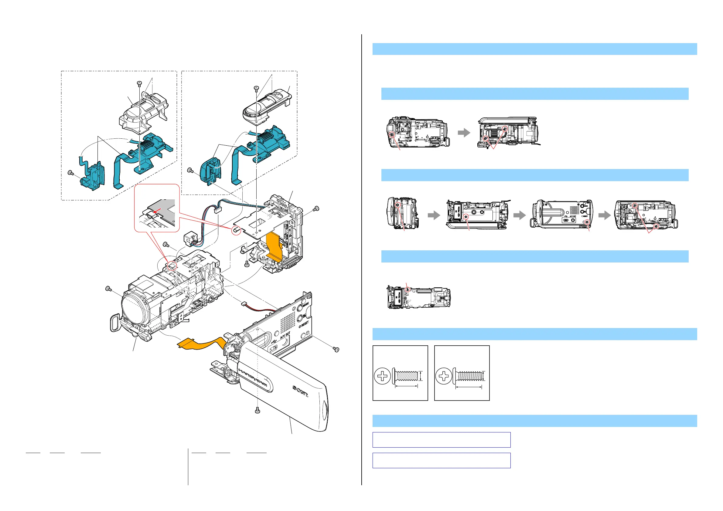
2-1-3. OVERALL SECTION-2
Ref. No. Part No. Description
Ref. No. Part No. Description
1. Remove to numerical order (1to 3) in the left figure.
DISASSEMBLY
1 101
(Note 2)
102
Lens Section
(See page 2-6)
2 Cabinet (R) Section
(See page 2-8)
(Note 1)
3 Battery Panel Section
(See page 2-7)
#2
#2
#12
#12
#12
#2
#2
#2
1 101
102
#2
#12
SX21/SX21ESR21/SR21E
Insert the front edge
into the aperture.
1 #12 X 1 → #2 X 2
Screw
Note
2 #2 X 3 → #12 X 2
Note 1: Refer to "Assembly-2: Installation Cautions of Speaker
Harness".
3 #2 X 1
#2
#12
Top Vi e wLeft View
#2
#2
#2
#12
Back View Bottom View Right View Left View
Bottom View
#2
#2: M1.7 X 4.0
(Black)
2-635-562-31
4.0
1.7
#12: M1.7 X 5.0 (Tapping)
(Black)
3-080-204-21
1.7
5.0
101 1-489-184-11 SWITCH BLOCK, CONTROL (PS24400) (SX21/SX21E)
(Note 2)
101 1-489-184-21 SWITCH BLOCK, CONTROL (PS24400) (SR21/SR21E)
102 4-209-702-01 CABINET (244), PS (SX21/SX21E)
102 4-209-703-01 CABINET (248), PS (SR21/SR21E)
#2 2-635-562-31 SCREW (M1.7)
#12 3-080-204-21 SCREW, TAPPING, P2
Note 2: Refer to "Assembly-7: Installation Cautions of the
Control Switch Block (PS24400) (SX21/SX21E)".