CD/DVD PLAYER
System
Laser: Semiconductor laser
Signal format system: PAL/NTSC
Audio characteristics
Frequency response: DVD VIDEO (PCM
96 kHz): 2 Hz to 44 kHz (±1.0 dB)/
DVD VIDEO (PCM 48 kHz): 2 Hz to
22 kHz (±0.5 dB)/CD: 2 Hz to 20 kHz
(±0.5 dB)
Signal-to-noise ratio (S/N ratio): 115 dB
(LINE OUT L/R (AUDIO) jacks only)
Harmonic distortion: 0.003%
Dynamic range: DVD VIDEO: 103 dB/
CD: 99 dB
Wow and flutter: Less than detected value
(±0.001% W PEAK)
Outputs
(Jack name: Jack type/Output level/
Load impedance)
LINE OUT (AUDIO): Phono jack/
2 Vrms/ 10 kilohms
DIGITAL OUT (OPTICAL)
(DVP-NS52P only):
Optical output jack/–18 dBm
(wave length 660 nm)
DIGITAL OUT (COAXIAL): Phono jack/
0.5 Vp-p/75 ohms
LINE OUT (VIDEO): Phono jack/
1.0 Vp-p/75 ohms
S VIDEO OUT
(DVP-NS52P only):
4-pin mini DIN/Y: 1.0 Vp-p,
C: 0.3 Vp-p (PAL),
0.286 Vp-p (NTSC)/75 ohms
COMPONENT VIDEO OUT
(Y, PB/CB, PR/CR)
(DVP-NS52P only):
Phono jack/Y: 1.0 Vp-p,
PB/CB, PR/CR: 0.7 Vp-p/75 ohms
SPECIFICATIONS
General
Power requirements:
220–240 V AC, 50/60 Hz
Power consumption:
DVP-NS32/NS33: 10 W
DVP-NS52P: 11 W
Dimensions (approx.):
DVP-NS32/NS33:
430 × 43 × 237.2 mm
DVP-NS52P:
430 × 43 × 237.3 mm
(width/height/depth)
incl. projecting parts
Mass (approx.):
DVP-NS32/NS33: 1.92 kg
DVP-NS52P: 1.95 kg
Operating temperature: 5°C to 35°C
Operating humidity: 25% to 80%
Supplied accessories
See page 15
Specifications and design are subject to
change without notice.
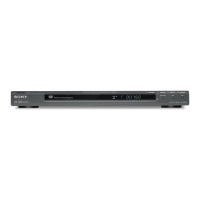
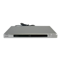
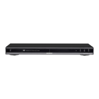
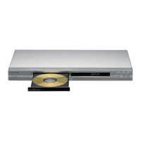
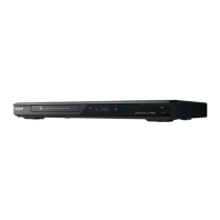
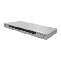
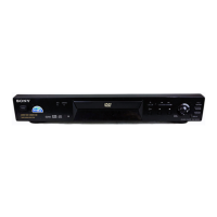
DVP-NS30/NS32/NS33/NS52P
RMT-D175P
SERVICE MANUAL
AEP Model
DVP-NS30/NS32/NS33/NS52P
Russia Model
DVP-NS30/NS32/NS52P
UK Model
DVP-NS30/NS52P
Photo : DVP-NS30
RMT-D175P
w
w
w
.
x
i
a
o
y
u
1
6
3
.
c
o
m
Q
Q
3
7
6
3
1
5
1
5
0
9
9
2
8
9
4
2
9
8
T
E
L
1
3
9
4
2
2
9
6
5
1
3
9
9
2
8
9
4
2
9
8
0
5
1
5
1
3
6
7
3
Q
Q
TEL 13942296513 QQ 376315150 892498299
TEL 13942296513 QQ 376315150 892498299
http://www.xiaoyu163.com
http://www.xiaoyu163.com