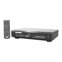
7-1
DVP-NS36/NS37/NS45P/NS55P/NS61P/NS63P
This section describes procedures and instructions necessary for
adjusting electrical circuits in this unit.
Instruments required:
(1) Color monitor TV
(2) Oscilloscope 1 or 2 phenomena, band width over 100 MHz, with
delay mode
(3) Frequency counter (over 8 digits)
(4) Digital multimeter
(5) Standard commander
(RMT-D175A/RMT-D175P/RMT-D175C)
(6) DVD reference disc
HLX-501 (J-6090-071-A) (dual layer) (NTSC)
HLX-503 (J-6090-069-A) (single layer) (NTSC)
HLX-504 (J-6090-088-A) (single layer) (NTSC)
HLX-505 (J-6090-089-A) (dual layer) (NTSC)
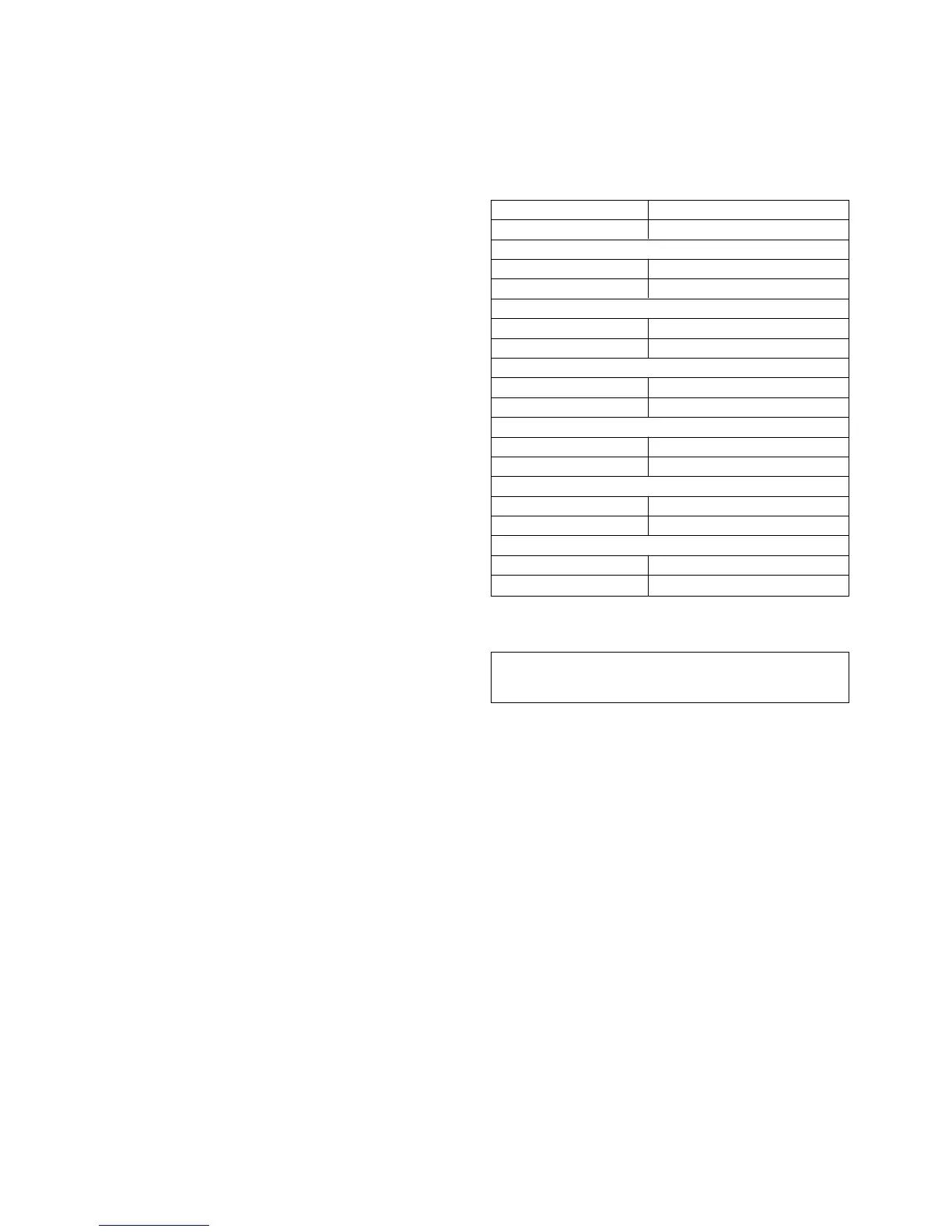
7-1. POWER SUPPLY OUTPUT VOLTAGE
CHECK
Mode Except standby
Instrument Digital multimeter
EVER +5 V Check
Test point CN201 pin 4
Specification 5.0 ± 0.3 Vdc
SW +3.3 V Check
Test point CN201 pin 5
Specification 3.35 ± 0.2 Vdc
SW+5 V Check
Test point CN201 pin 6
Specification 5.0 Vdc
SW +8 V Check
Test point CN201 pin 1
Specification 8.0 ± 0.5 Vdc
EVER +11 V Check
Test point CN201 pin 3
Specification 11.0 Vdc
EVER –10 V Check
Test point CN201 pin q;
Specification –10.0 Vdc
Checking method:
(1) Confirm that each voltage satisfies the specification.
Caution!
Please do not touch any electrical parts at primary circuit to avoid
electrical shock.
+0.5
–1.0
+1.0
–0.5
+0.2
–0.3
SECTION 7
ELECTRICAL ADJUSTMENT
 Loading...