7-4
DVP-NS36/NS37/NS45P/NS55P/NS61P/NS63P
1.0 ± 0.08 Vp-p
7-3. ADJUSTMENT OF VIDEO SYSTEM
(EXCEPT DVP-NS36:AEP,UK/NS37)
1. Checking Video Level
<Purpose>
Checking Video Level the NTSC/PAL standard, and if not correct, the
brightness will be too large or small.
Mode HLX-504 play back
Signal Color bars 100%
Test point LINE OUT (VIDEO) connector
(75 Ω terminated)
Instrument Oscilloscope
Specification 1.0 ± 0.08 Vp-p
Adjusting method:
(1) In the Video Signal menu “1” Color Bar 100% play back.
(2) Confirm that the Video Level is 1.0 ± 0.08 Vp-p.
Fig. 7-1.
2. Checking Progressive Video Output Level
<Purpose>
Check progressive video output level. If it is incorrect, correct
brightness will not be attained when connected to, for instance,
projector.
Mode HLX-504 play back
Signal Color bars 100%
Test point COMPONENT VIDEO OUT (Y)
connector (75 Ω terminated)
Instrument Oscilloscope
Specification 1.0 ± 0.08 Vp-p
Adjusting method:
(1) In the Video Signal menu “1” Color Bar 100% play back.
(2) Confirm that the Y level is 1.0 ± 0.08 Vp-p.
Fig. 7-2.
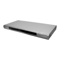
3. Checking S Video Output S-Y
<Purpose>
Check S-terminal video output. If it is incorrect, pictures will not be
displayed correctly in spite of connection to the TV with a S-terminal
cable.
Mode HLX-504 play back
Signal Color bars 100%
Test point S VIDEO OUT (S-Y) connector
(75 Ω terminated)
Instrument Oscilloscope
Specification 1.0 ± 0.08 Vp-p
Checking method:
(1) In the Video Signal menu “1” Color Bar 100% play back.
(2) Confirm that the S-Y level is 1.0 ± 0.08 Vp-p.
Fig. 7-3.
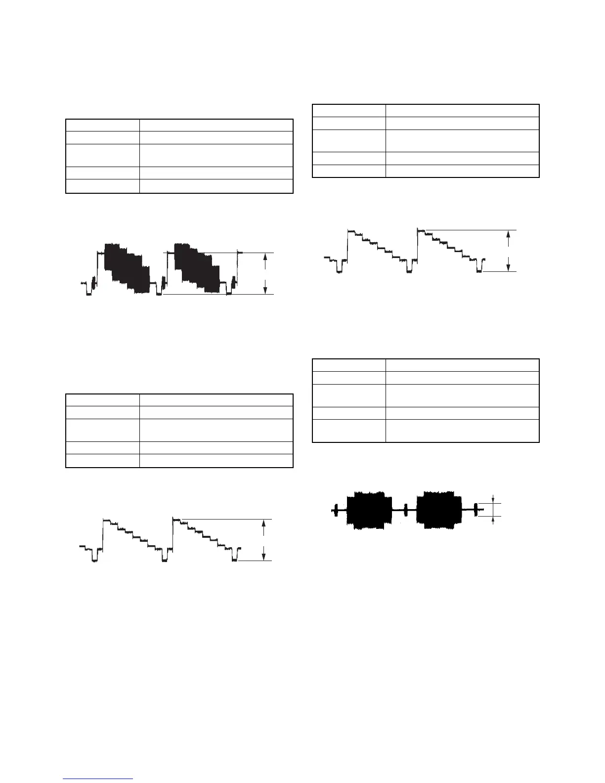
4. Checking S Video Output S-C
<Purpose>
This checks whether the S-C satisfies the NTSC/PAL standard. If it is
not correct, the colors will be too dark or light.
Mode HLX-504 play back
Signal Color bars 100%
Test point S VIDEO OUT (S-C) connector
(75 Ω terminated)
Instrument Oscilloscope
Specification A = 286 ± 50 mVp-p (NTSC)
A = 300 ± 50 mVp-p (PAL)
Checking method:
(1) In the Video Signal menu “1” Color Bar 100% play back.
(2) Confirm that the S-C burst is “A”.
Fig. 7-4.
A
1.0 ± 0.08 Vp-p
1.0 ±0.08 Vp-p
 Loading...