7-5
DVP-NS36/NS37/NS45P/NS55P/NS61P/NS63P
1.0 ±0.08 Vp-p
A
B
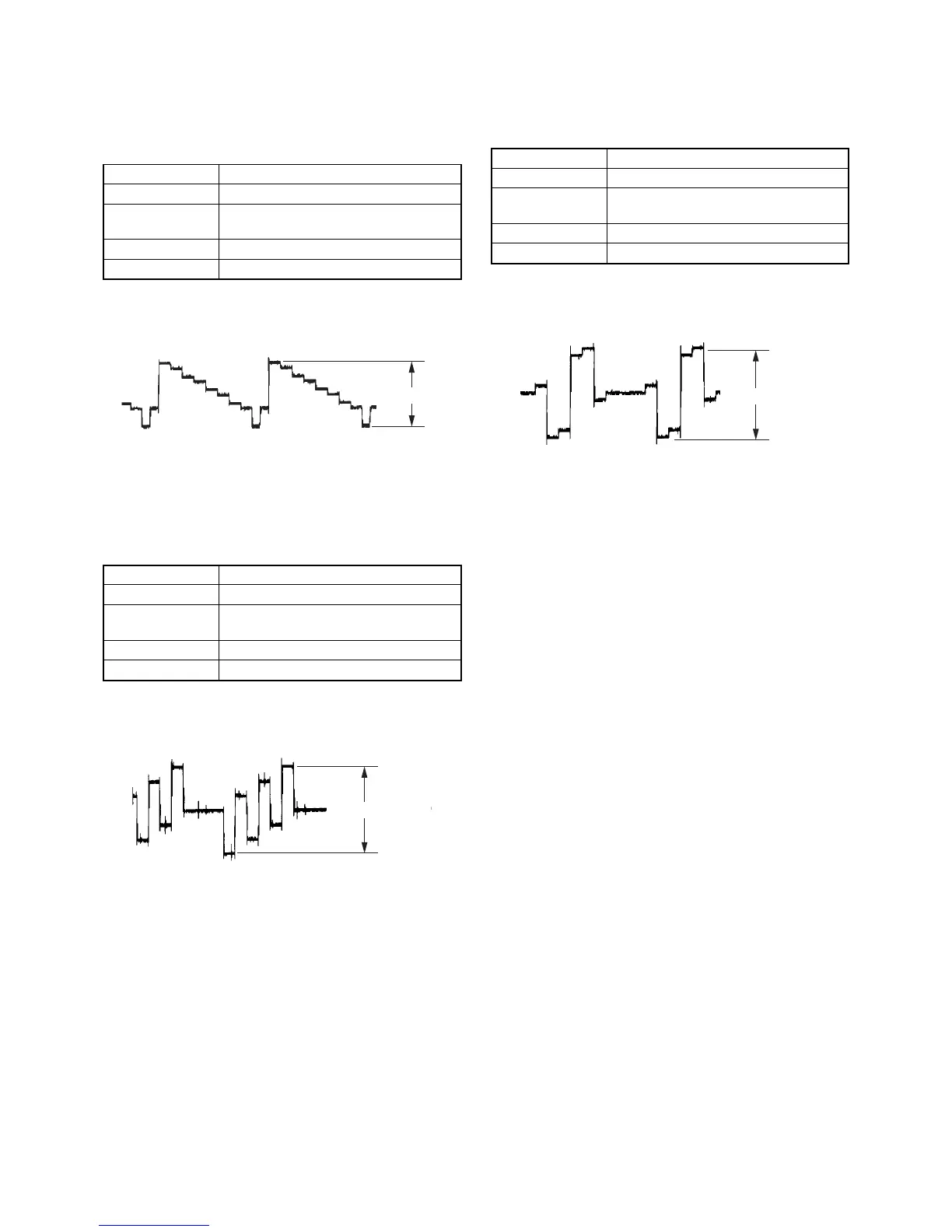
5. Checking Component Video Output Y
<Purpose>
This checks component video output Y. If it is incorrect, correct
brightness will not be attained when connected to, for instance,
projector.
Mode HLX-504 play back
Signal Color bars
Test point COMPONENT VIDEO OUT (Y)
connector, (75 Ω terminated)
Instrument Oscilloscope
Specification 1.0 ± 0.08 Vp-p
Checking method:
(1) In the Video Signal menu “1” Color Bar 100% play back.
(2) Confirm that the Y level is 1.0 ± 0.08 Vp-p.
Fig. 7-5.
6. Checking Component Video Output B-Y
<Purpose>
This checks component video output B-Y. If it is incorrect, correct
colors will not be displayed when connected to, for instance, projector.
Mode HLX-504 play back
Signal Color bars
Test point COMPONENT VIDEO OUT (PB)
connector (75 Ω terminated)
Instrument Oscilloscope
Specification A = 700 ± 70 mVp-p
Checking method:
(1) In the Video Signal menu “1” Color Bar 100% play back.
(2) Confirm that the B-Y level is A.
Fig. 7-6.
7. Checking Component Video Output R-Y
<Purpose>
This checks component video output R-Y. If it is incorrect, correct
colors will not be displayed when connected to, for instance, projector.
Mode HLX-504 play back
Signal Color bars
Test point COMPONENT VIDEO OUT (PR)
connector (75 Ω terminated)
Instrument Oscilloscope
Specification B = 700 ± 70 mVp-p
Checking method:
(1) In the Video Signal menu “1” Color Bar 100% play back.
(2) Confirm that the R-Y level is B.
Fig. 7-7.
7-5E
 Loading...