No.
Pin
Name
35
OUT DC DET
36
B OUT
37
N.C.
38
RGB AMP
39
FRP
40
RGB INV
41
SUB BRT B
I/O
Description
I
The capacitance which smoothes and protects the difference of the output DC bias
from
(VCC
+ VEE) /2.
0 The inverted primary color signal is output according to the inversion signal.
Not used.
I
The amplitude between the normal and inverted RGB output can be adjusted. This
pin is preset in the IC.
I
The inversion signal is input.
I
GND
I
The brightness of the B signal can be finely adjusted by the DC voltage which is
input to this pin. This pin is preset in the IC.
42
SUB BRT R
43
BRIGHT
44 GAMMA 2
The brightness of the R signal can be finely adjusted by the DC voltage which is
input to this pin. This pin is preset in the IC.
The Y-signal can be adjusted by the DC voltage which is input to this pin.
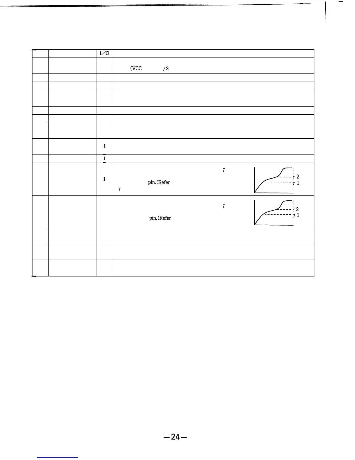
The change point of the DC voltage gain of
7
PEAK
OUTPUT
LIMITER
correction can be set by the DC voltage which is
-mm-
input to this
pin.(Refer
to the’ right figure.) The
72
7
-correction pin is preset in the IC.
If/
---------
71
45
GAMMA 1
I
INPUT
PEAK
The change point of the DC voltage gain of
7
OUTPUT
LIMITER
correction can be set by the DC voltage which is
----72
input to this
pin.(Refer
to the right figure.)
GL
---------
7
1
INPUT
46
PEAK LIM
I
The peak limiter level on the white peak of the primary color output can be set by
the DC voltage which is input to this pin.
47
SUB CONT B
I
48
SUB CONT R
I
The contrast of the B signal can be finely adjusted by the DC voltage which is input
to this pin. This pin is preset in the IC.
The contrast of the R signal can be finely adjusted by the DC voltage which is input
to this pin. This pin is preset in the IC.
-26